IR Remote tester in use, showing a remote control lighting up an LED and screenshots of the Arduino serial terminal

IR Remote Tester Helps You Crack The Code

Even though some devices now use WiFi and Bluetooth, so much of our home entertainment equipment still relies on its own proprietary infrared remote control. By and large (when you can find them) they work fine, but what happens when they stop working?  First port of call is to change the batteries, of course, but once you’ve tried that what do you do next? [Hulk] has your back with this simple but effective IR Remote Tester / Decoder.

IR remote tester schematic showing arduino, receiver, LED and resistor
How to connect the TSOP4838 to an Arduino to read the transmitted codes

By using a cheap integrated IR receiver/decoder device (the venerable TSOP4838), most of the hard work is done for you! For a quick visual check that your remote is sending codes, it can easily drive a visible LED with just a resistor for a current-limit, and a capacitor to make the flickering easier to see.

For an encore, [Hulk] shows how to connect this up to an Arduino and how to use the “IRremote” library to see the actual data being transmitted when the buttons are pressed.

It’s not much of a leap to imagine what else you might be able to do with this information once you’ve received it – controlling your own projects, cloning the IR remote codes, automating remote control sequences etc..

It’s a great way to make the invisible visible and add some helpful debug information into the mix.

We recently covered a more complex IR cloner, and if you need  to put together a truly universal remote control, then this project may be just what you need.

Continue reading “IR Remote Tester Helps You Crack The Code”

"The Great Resistor" color code illumination project

The Great Resistor Embiggens The Smallest Value

With surface-mount components quickly becoming the norm, even for homebrew hardware, the resistor color-code can sometimes feel a bit old-hat. However, anybody who has ever tried to identify a random through-hole resistor from a pile of assorted values will know that it’s still a handy skill to have up your sleeve. With this in mind, [j] decided to super-size the color-code with “The Great Resistor”.

Resistor color code from Wikipedia with white background
How the resistor color-code bands work

At the heart of the project is an Arduino Nano clone and a potential divider that measures the resistance of the test resistor against a known fixed value. Using the 16-bit ADC, the range of measurable values is theoretically 0 Ω to 15 MΩ, but there are some remaining issues with electrical noise that currently limit the practical range to between 100 Ω and 2 MΩ.

[j] is measuring the supply voltage to help counteract the noise, but intends to move to an oversampling/averaging method to improve the results in the next iteration.

The measured value is shown on the OLED display at the front, and in resistor color-code on an enormous symbolic resistor lit by WS2812 RGB LEDs behind.

Inside view of the great resistor showing WS2812 LEDs and baffle plates
Inside The Great Resistor, the LEDs and baffle plates make the magic work

Precision aside, the project looks very impressive and we like the way the giant resistor has been constructed. It would look great at a science show or a demonstration. We’re sure that the noise issues can be ironed out, and we’d encourage any readers with experience in this area to offer [j] some tips in the comments below. There’s a video after the break of The Great Resistor being put through its paces!

If you want to know more about the history of the resistor color code bands, then we have you covered.  Alternatively, how about reading the color code directly with computer vision?

Continue reading “The Great Resistor Embiggens The Smallest Value”

Walnut Case Sets This Custom Arduino-Powered RPN Calculator Apart From The Crowd

How many of us have an everyday tool that’s truly unique? Likely not many of us; take a look around your desk and turn out your pockets, but more often than not, what you’ll find is that everything you have is something that pretty much everyone else on the planet could have bought too. But not so if you’ve got this beautiful custom RPN calculator in a wooden case.

This one comes to us from [Shinsaku Hiura], who generally dazzles us with unique mechanical clocks and displays. This calculator solves a more practical problem — the dearth of RPN calculators on the market with the correct keyboard feel, specifically with the large keys and light touch he desired. Appropriately, the build started with a numeric keypad, which once liberated of its USB interface was reverse-engineered to figure out how the matrix was wired. Next up, a custom PCB to connect the keypad to an Arduino and a 20×4 LCD display was milled up, while a test case was designed and printed to check fitment. The final case was milled from a block of solid walnut and fitted with an acrylic window, for a sharp look with clean lines and pleasing colors.

As for the calculator itself, the demo below shows it going through its paces. The code is clever because it leverages the minimal number of keys available by hiding all the scientific and engineering functions behind a “secret silver key” that was once the equals key and obviously not needed in RPN. Hats off to [Shinsaku] for a handsome and unique addition to his desk.

Continue reading “Walnut Case Sets This Custom Arduino-Powered RPN Calculator Apart From The Crowd”

A personal computer drive bay with a glowing LED display

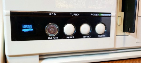
Turbo Button Pays Charming Homage To Early Personal Computers

The PC turbo button and LED clock speed display were common features on early personal computers. Wanting to add a little retro chic to his modern battle-station, [Matthew Frost] assembled a charming and functional homage to the turbo button control panel.

In days past, this automotive nomenclature implied a performance boost when activated. Instead, ‘turbo mode’ would clock your x86 processor at its rated speed. Disabling ‘turbo’ would throttle the CPU, often all the way down to 4.77MHz. Inherited from the original IBM PC, some early computer programs relied on this specific clock speed, and would otherwise run too fast (or not at all) on faster hardware. PC marketing teams and engineers alike stopped including the turbo button and glowing clock speed numbers around the Pentium era.

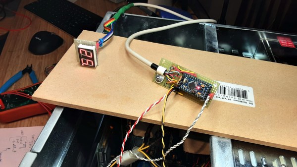
This modern re-imagining of the turbo button uses an Arduino microcontroller, seven-segment display and tactile switches to emulate the look and feel of the original hardware. Instead of directly adjusting the CPU clock speed, hitting turbo switches between balanced and high-performance Windows power plans. The seven-segment display measures this clock speed in GHz to two decimal places. We’ll admit that it’s pretty satisfying to see those numbers inch higher when switching to turbo.

The rightmost button switches between measuring CPU speed, GPU utilization, network load and memory utilization, which improves on its original inspiration. The tubular key lock, also a common sight on early PCs, enables and disables networking for the entire system, which is great for keeping the kids off the ‘net (at least until they figure out how to remove the 5.25″ drive bay from the system and hot-wire the network adapter with a paperclip).

There are more details on the GitHub page, in case you want to build your own. This project could look especially fetching in PC sleeper builds, where new components are ‘hidden’ in old case hardware. And if this has made you feel nostalgic at all, you may want to hear our thoughts on why it’s all about the Pentiums.

Continue reading “Turbo Button Pays Charming Homage To Early Personal Computers”

Garmin HUD Got Discontinued, But Not Trashed

The Garmin HUD+ was a small Bluetooth device intended for the dashboard of a car, meant to be used as a GPS heads-up display for data from Garmin smartphone apps. It used a bright VFD (vacuum fluorescent display) which was viewed through a clear reflector, and displayed GPS information and directions. It was discontinued in 2015, but [Doz] was fond of his and used it happily until a phone upgrade meant it no longer worked. Was it destined for a landfill? Not if he had anything to say about it!

The first thing [Doz] tried was using an alternate Android app, but since it also didn’t work, it was time to sit back and reflect on the scope of the issue. In [Doz]’s case, he really only wanted some basic meaningful data displayed, and decided he could do away with the phone altogether if he had the right hardware. Continue reading “Garmin HUD Got Discontinued, But Not Trashed”

ESP8266 Web Server Saves 60% Power With A 1 Ms Delay

Arduino has a library for quickly and easily setting up a simple web server on an ESP8622-based board, and [Tomaž] found that power consumption on an ESP-01 can be reduced a considerable amount by simply inserting a 1 ms delay in the right place. The reason this works isn’t because of some strange bug or oddball feature — it’s really just a side effect of how the hardware operates under the hood.

[Tomaž] uses the “hello world” example from ESP8266WebServer to explain. In it, the main loop essentially consists of calling server.handleClient() forever. That process checks for incoming HTTP connections, handles them, sends responses, exits — and then does it all over again. A simple web server like this one spends most of its time waiting.

A far more efficient way to handle things would be to launch server.handleClient() only when an incoming network connection calls for it, and put the hardware to sleep whenever that is not happening. However, that level of control just isn’t possible in the context of the Arduino’s ESP8266WebServer library.

So what’s to be done? The next best thing turns out to be a simple delay(1) statement right after each server.handleClient() call in the main loop.

Why does this work? Adding delay(1) actually causes the CPU to spend the vast majority of its time in that one millisecond loop. And counting microseconds turns out to be a far less demanding task, power-wise, than checking for incoming network requests about a hundred thousand times per second. In [Tomaž]’s tests, that one millisecond delay reduced idle power consumption at 3.3 V from roughly 230 mW to around 70 mW — about 60% — while only delaying the web server’s response times by 6-8 milliseconds.

For simple web server applications, this is is for sure a good trick to keep in mind. There are also much more advanced techniques for saving power on ESP8266-based boards; from boards that barely sip a single microamp while sleeping, to coin-cell powered boards that go so far as to modify the TCP/IP stack to help squeeze every bit of power savings possible.

One Of The Worst Keyboards Ever, Now An Arduino Peripheral

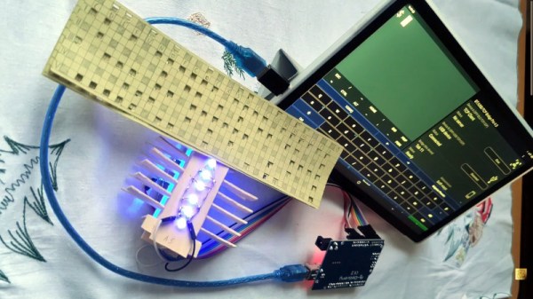
For British kids of a certain age, their first experience of a computer was very likely to have been in front of a Sinclair ZX81. The lesser-known predecessor to the wildly-successful ZX Spectrum, it came in at under £100 and sported a Z80 processor and a whopping 1k of memory. In the long tradition of Sinclair products it had a few compromises to achieve that price point, the most obvious of which was a 40-key membrane keyboard. Those who learned to code on its frustrating lack of tactile feedback may be surprised to see an Arduino project presenting it as the perfect way to easily hook up a keyboard to an Arduino.

Like many retrocomputing parts, the ZX81 ‘board has been re-manufactured, to the joy of many a Sinclair enthusiast. It’s thus readily available and relatively cheap (we think they can be found for less than the stated 20 euros!), so surprisingly it’s a reasonable choice for an Arduino project. The task of trying to define by touch the imperceptible difference in thickness of a ZX81 key will bring a true retrocomputing experience to a new generation. Perhaps if it can be done on an Mbed then someone might even make a ZX81 emulator on the Arduino.

We’re great fans of the ZX81 here at Hackaday, for some of us it was that first computer. Long may it continue to delight its fans!