A tachometer used to be an accessory added to the dash of only the sportiest of cars, but now they’re pretty much standard equipment on everything from sleek coupes to the family truckster. If your daily driver was born without a tach, fear not – a simple Arduino tachometer is well within your reach.
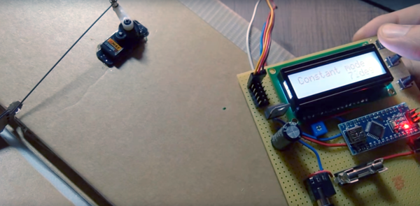
The tach-less vehicle in question is [deepsyx]’s Opel Astra, which from the video below seems to have the pep and manual transmission that would make a tach especially useful. Eschewing the traditional analog meter display or even a digital readout, [deepsyx] opted to indicate shift points with four LEDs mounted to a scrap of old credit card. The first LED lights at 4000 RPM, with subsequent LEDs coming on at each 500 RPM increase beyond that. At 5800 RPM, all the LEDs blink as a redline warning. [Deepsyx] even provides a serial output of the smoothed RPM value, so logging of RPM data is a possible future enhancement.
The project is sensing engine speed using the coil trigger signal – a signal sent from the Engine Control Unit (ECU) which tells one of the ignition coilpacks to fire. The high voltage signal from the coilpack passes on to the spark plug, which ignites the air-fuel mixture in that cylinder. This is a good way to determine engine RPM without mechanical modifications to the car. Just make sure you modify the code for the correct number of cylinders in your vehicle.
Simple, cheap, effective – even if it is more of a shift point indicator than true tachometer, it gets the job done. But if you’re looking for a more traditional display and have a more recent vintage car, this sweeping LED tachometer might suit you more.
Continue reading “Quick Arduino Hack Lets Tach-less Car Display Shift Points” →