Programming An Arduino Over WiFi With The ESP8266

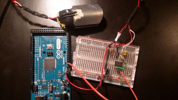
A lot of people have used ESP8266 to add inexpensive WiFi connectivity to their projects, but [Oscar] decided to take it one step further and program an Arduino over WiFi with the ESP8266. [Oscar] wrote a server script in Python that communicates with firmware running on the Arduino. The Arduino connects to the server on startup and listens for a “reboot” command.

When the command is received, the processor resets and enters the bootloader. The python script begins streaming a hex file over WiFi to the ESP8226, which relays it to the Arduino’s bootloader. Once the hex file is streamed, the microcontroller seamlessly starts executing the firmware. This method can be used with any AVR running a stk500-compatible bootloader.

[Oscar]’s writeup is in Spanish, but fortunately the comments in his Python and Arduino code are in English. Check out the video (in English) after the break where [Oscar] demonstrates his bootloading setup.

Continue reading “Programming An Arduino Over WiFi With The ESP8266”

Mobile Planter Chases The Sun

There are two types of people: ones with green thumbs, and ones that kill their cacti  because they forgot to water them for over a year. Sadly, we are of the latter group. We currently have a resilient spider plant that looks like it could use more sun. Now there’s a way for it to catch those rays wherever they may shine, thanks to [Dot Matrix] of Instructables. She made a mobile planter that actively seeks out sunlight.

The planter’s base was made of plywood, topped with fake grass and a watering can to hold the plant. Anything above the planter base can be modified to whatever desired aesthetic. A CRT planter may be too heavy, but there are countless ways to personalize it. [Dot] used an Afinia 3D printer to make various mounts and brackets with ABS plastic. The planter was controlled by an Arduino Micro and used a pair of 0.5W solar panels and Parallax PING))) sensors to decide how it should move from its current position. If the planter would fall or hit an object moving forward, it would reverse and turn on wheels powered by Parallax continuous rotation servos. It would evaluate its new position, repeating the process if it was in danger. Once the planter was safe, it used the solar panels to detect the most sunlight: the sum of the panels determines the area’s brightness while the individual panels’ readings were used to move the planter towards a brighter area. The sun-seeking continued until the sunniest spot was found (defined in the code). Here, the planter remained idle for 10 minutes before restarting the process.

We think [Dot’s] planter is a fun way to keep plants happy and healthy in spite of us. See a video of the planter after the break.

Continue reading “Mobile Planter Chases The Sun”

Monitor Shield Leaves No Pin Unused

What doesn’t this Arduino Mega shield have? Ponder that as you realize that it doesn’t just attach itself to the pin headers, but uses every single one of the mega’s connections.

This isn’t a bunch of components kludged together either. [Carsten] is an a EE and that explains a lot of the really great choices he made like buffering, opto-isolation, and the clean assembly despite a schematic that’s so busy it’s difficult figure out where to start.

So, what does it do? Looks like a one-stop-shop for quick prototyping needs. For instance, there’s a pushbutton, toggle-switch, and a couple of trimpots for quick and easy input. At the center of the board is a 7-segment display, and multiple rows of LED bar displays (assembled from SMD components and protoboard) to provide feedback to the user.

There are also a number of sensors at the party, including a mercury shake sensor, temperature sensor, microphone, thermistor, and light dependent resistor. If what you need isn’t on the board there are multiple options for connecting external gear including opto-isolated input and output, and a LEMO for digital I/O with another for analog. All of that and we forgot to mention the moving coil voltmeter that measures PWM.

Dog Tracker Knows Where The Dirt Is

[Eric] is well on his way to making one of the less pleasant chores of pet ownership a bit easier with his dog tracking system. The dog tracker is actually a small part of [Eric’s] much larger OpenHAB system, which we featured back in July.

As a dog owner, [Eric] hates searching the yard for his pet’s droppings. He had been planning a system to make this easier, and a local hackerspace event provided just the opportunity to flesh his ideas out. The Dog Tracker’s primary sensor is a GPS. Most dogs remain motionless for a few seconds while they go about their business. [Eric’s] Arduino-frgbased system uses this fact, coupled with a tilt sensor to determine if the family pet has left any presents.

The tracker relays this information to the home base station using a HopeRF RFM69 transceiver. The RFM69 only has about a 900 foot range, so folks with larger properties will probably want to spring for a cellular network based tracking system. Once the droppings have been tracked, OpenHAB has an interface

[Eric] has also covered runaway dogs in his design. If Fido passes a geo-fence, OpenHAB will raise the alarm. A handheld dog tracker with its own RFM69 can be used to chase down dogs on the run. Future plans are to miniaturize the dog tracker such that it will be more comfortable for a dog to wear.

Continue reading “Dog Tracker Knows Where The Dirt Is”

Talking Tactile 3D Prints

Cell biology professor [Mike] has created a way for blind students to decipher microscope slides using 3D prints and the magic of capacitive sensing. His write-up focuses on a slide showing the anaphase stage of mitosis in whitefish blastula, a popular choice for studying cell division. When a student touches a certain area of the print, the capacitive sensor triggers audio playback to tell them what they’re feeling.

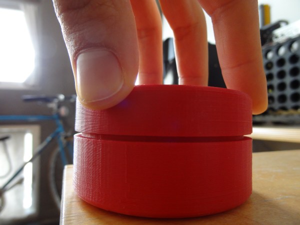
[Mike] started by turning a 2D image of a cell into a 3D print. To do this, he made the image black and white, and then inverted the colors so that the 3D print’s topography will correspond correctly. The talking part is handled by an Arduino Duemilanove and a Spikenzie voice shield. The latter has a somewhat limited amount of space, but is more than adequate for the audio labels [Mike] made, which are all less than three seconds long.

A hard copy of the 2D file comes in handy for making sure the cap sensors are in the right places. To make those, [Mike] cut up some floor protector pads and covered the sticky side with copper tape. These are held on the 2D image with double-sided tape. The 3D print sits on top, separated by more furniture pads at the corners. He labeled this scientific sandwich model with a 3D printed Braille label that reads ‘anaphase’. [Mike] has made the referenced STL file along with a few others available at the National Institutes of Health’s 3D print exchange site.

Using Router SoCs As WiFi Modules (Yet Again)

8-bit AVRs and 32-bit ARMs do one thing, and one thing well: controlling other electronics and sensors while sipping power. The Internet of Things is upon us and with that comes the need for connecting to WiFi networks. Already, a lot of chips are using repackaged System on Chips to provide an easy way to connect to WiFi, and the USR-WIFI232-T is the latest of the bunch. It’s yet another UART to WiFi bridge, and as [2XOD], it’s pretty easy to connect to an AVR.

The module in question can be had through the usual channels for about $11, shipped straight from China, and the only purpose of this device is to provide a bridge between a serial port and a wireless network. They’re not that powerful, and are only meant for simple tasks,

[2XOD] got his hands on one of these modules and tested them out. They’re actually somewhat interesting, with all the configuration happening over a webpage served from the device. Of course the standard AT commands are available for setting everything up, just like the ESP8266.

With a month of testing, [2XOD] has found this to be a very reliable device, logging temperatures every minute for two weeks. There’s also a breakout board available to make connection easy, and depending on what project you’re building, these could be a reasonable stand-in for some other popular UART -> WiFi chips.

Undershield, DIY Arduino Battery Shield

Battery Shield Mounts Underneath The Arduino

So, what do you do when your Arduino project needs to operate in a remote area or as a portable device? There are LiPo battery shields available, and although they may work well, recharging requires access to a USB port. You can also go the 9v battery route plugged into the on-board regulator of the Arduino but the low mAh rating of a 9v won’t allow your project to stay running for very long. [AI] needed a quick-change battery option for his Arduino project and came up with what he is calling the AA Undershield.

As the name implies, AA sized batteries are used in the project, two of them actually. Yes, two AA batteries at 1.5v each would equal only 3 volts when connected in series. The Arduino needs 5v so [AI] decided to use a MAX756 DC-to-DC step-up regulator to maintain a steady stream of 5v. This article has some nice graphs showing the difference in performance between a 9v battery being stepped down to 5v verses two AA’s being bumped up to 5v.

The ‘under’ in Undershield comes from this shield being mounted underneath the Arduino, unlike every other shield on the planet. Doing so allows use of a standard 0.100″-spaced prototype PCB and is an easy DIY solution to that odd-sized space between the Arduino’s Digital 7 and 8 pins. The Arduino mounts to the Undershield via its normal mounting holes with the help of some aluminum stand offs.

[AI] did a great job documenting his build with schematics and lots of photos so that anyone that is interested in making one for themselves can do so with extreme ease.