A STM32F4 Based Arduino In The Feather Form Factor

[minh7a6] loves the Adafruit Feather, but sees some room for improvement.

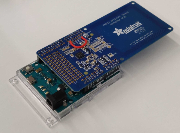
First is the matter of 5V tolerance. While just about everything is available in a 3.3v range these days, sometimes it’s just nice not to have to care. The main controller on the Feather is plenty powerful, but its intolerant pins just wouldn’t do so it was swapped for a chip from the ever popular STM32F4 line.

Then he wanted better energy efficiency when running from battery. In order to achieve this he switched from a linear regulator to a buck-boost converter. He also felt that the need for a separate SWD adapter for debugging seemed unnecessary, so he built a Black Magic Probe right in.

He’s just now finishing up the Arduino IDE support for the board, which is pretty cool. There’s no intention to produce this souped up Feather, but all the files are available for anyone interested.

In Case You Cannot Make It To An Escape Room

Escape rooms are awesome for people who like to solve puzzles, see how things work, or enjoy a mystery. Everyone reading this falls into at least one of those categories. We enjoy puzzles and mysteries, but we have a fondness for seeing how things work. To this end, we direct your attention to [doktorinjh]’s “Bomb Disarming Puzzle in a Suitcase” Game, which is a mysterious puzzle box he built himself. I guess the mystery is mostly in the gameplay, which you can watch below because he shows us his build photos and describes the hardware inside.

At its heart is an Arduino Mega, a wise choice since our back-of-the-napkin estimation puts his I/O count over forty-five and the Mega can handle them all with a few pins to spare. Working inside the confines of a briefcase came with its own challenges, but we adore the way he used the hexagon theme in the top panel to allow for knob clearance. It was so subtle that we almost missed it.

The escape room theme is delightful, and we appreciate the mix of games, aesthetics, and techno-trickery in many forms.

Continue reading “In Case You Cannot Make It To An Escape Room”

Keeping Time With Blinkenlights

If we’ve learned anything over the years, it’s that hackers like weird clocks, and they love packing as many multicolored LEDs into a device as is humanly possible. Combine both of those concepts into one project, and you’ve got a perfect storm. So as far as unnecessarily complex timepieces go, we’d say the “Crazy Clock 4” built by [Fearless Night] ranks up there among the all-time greats.

This Arduino Pro Mini powered clock syncs the current time via GPS, with a temperature compensated DS3231 RTC to keep it on the straight and narrow between satellite downlinks. Once the clock has the correct time, how do you read it? Well, at the top you’ve got a basic numerical readout for the normies, and next to that there’s a circular LED display that looks like it could double as a sci-fi movie prop. On the lower level there’s a binary clock for the real show-offs, and as if that wasn’t enough, there’s even dual color-coded analog meters to show the hours and minutes.

[Fearless Night] has provided everything you need to follow along at home, from the Arduino source code to the 3D models of the case and Gerber files for the custom PCB. Personally we think just the top half of the clock would be more than sufficient for our timekeeping needs. If nothing else it should help save some energy, as the clock currently pulls an incredible 20 watts with all those LEDs firing off.

Should you decide to take a walk down memory lane and check out some of the other interesting LED clocks we’ve featured in the past, you’d be busy for quite awhile. But for our money, it’s still hard to beat the impossibly obtuse single-LED clock.

Bamboo Skewers Launch Airship

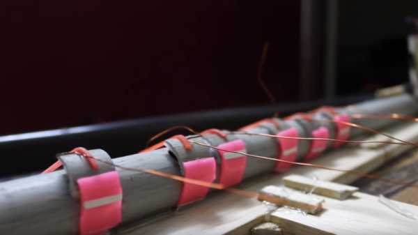
We have to admit, we like airships. There’s something about the image of a stately zeppelin floating over Manhattan that just makes us imagine the future. There are not many airships anymore, but you can always build your own. [Crafty Robot] shows how to use one of their boards to make a simple and easy controlled balloon. Honestly, they don’t give you many details, but we know how to turn motors and servos. We loved their construction with hot glue and bamboo. Effective, and fun to say.

The bamboo skewers are easy to find and make a lightweight frame. Some drone motors provide thrust and some simple RC servos control the angle of the props. Nice and simple.

Continue reading “Bamboo Skewers Launch Airship”

SiCK Mechanical Keyboard Is 3D Printed

We’ve noticed a rash of builds of [ FedorSosnin’s] do-it-yourself 3D-printed mechanical keyboard, SiCK-68 lately. The cost is pretty low — SiCK stands for Super, Inexpensive, Cheap, Keyboard. According to the bill of materials, the original cost about $50. Of course, that doesn’t include the cost of the 3D printer and soldering gear, but who doesn’t have all that already?

The brains behind this is a Teensy that scans the hand-wired key matrix. So the only electronics here are the switches, each with a companion diode, and the Teensy. The EasyAVR software does all the logical work both as firmware and a configuration GUI.

If you look at the many different builds, each has its own character. Yet they look overwhelmingly professional — like something you might buy at a store. This is the kind of project that would have been extremely difficult to pull off a decade ago. You could build the keyboard, of course, but making it look like a finished product was beyond most of us unless we were willing to make enough copies to justify having special tooling made to mold the cases.

PCBs are cheap now and we might be tempted to use one here. There are quite a few methods for using a 3D printer to create a board, so that would be another option. The hand wiring seems like it would be a drag, although manageable. If you need wiring inspiration, we can help.

For ultimate geek cred, combine this with Ploopy.

Rotary Dial Becomes USB Keyboard

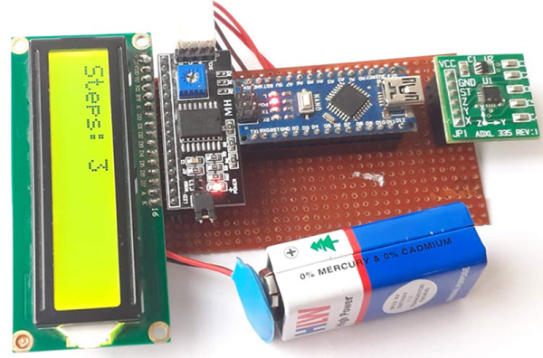
[Max] had a rotary dial from an old telephone and — unsurprisingly — had nothing in particular to do with it. The simple answer? Use an Arduino Leonardo to turn it into a USB keyboard device.

Of course, the Leonardo can easily impersonate a USB keyboard, so that’s the easy part of the project. Interfacing to the dial requires an understanding of how the phone system works.

While today, TouchTone phones are most common, they were quite uncommon for many years. Early phones required you to have an operator connect your circuit to another person’s circuit. Unfortunately for the operators, the system was inherently unscalable and also cost prohibitive.

There were a variety of schemes tried and — supposedly — an undertaker who was angry that the operator was connecting his customers to her husband’s competing mortuary invented the dial telephone.

The details are pretty simple. A typical dial has two contacts. There’s a normally open contact that closes when you spin the dial to any position. It says closed until the spring returns the dial to the home position.

The other contact is normally closed and makes or breaks the phone line. Each time the dial rewinds past a position, the contact opens briefly. Of course, this is a mechanical system, so the software has to debounce the inputs, but that’s easy enough.

If you don’t have access to a dial, you could always print one. Sort of.

Arduino Does Multitouch

A lot of consumer gadgets use touch sensors now. It is a cheap and reliable way to replace a variety of knobs and switches on everything from headphones to automobiles. However, creating a custom touch controller for a one-off project can be daunting. A recent ACM paper shows how just about any capacitive sensor can work as a multitouch sensor with nothing more than an Arduino although a PC running processing interprets the data for higher-level functions.

The key is that the Arduino excites the grid using PWM and then examines the signal coming out of the grid. Finger poking changes the response quite a bit and the Arduino can sense it using the analog to digital converters onboard. You can find the actual software kit online. The tutorial document is probably more interesting than the ACM paper if you only want to use the kit.

The optimum drive frequency is 10 MHz. The examples rely on harmonics of a lower frequency PWM signal to get there. The analog conversion, of course, isn’t that fast but since your finger touch rate is relatively slow, they treat the signal as an amplitude-modulated input which is very easy to decode.

The sensors can be conductive ink, thread, or copper strips. There are several example applications, including a 3D printed bunny you can pet, a control panel on a sleeve, and an interactive greeting card.

The sensor forms an image and OpenCV detects the actual touch configuration. It appears you can use the raw data from the Arduino, too, but it might be a little harder.

We imagine aluminum foil would work with this technique. If you get to the point of laying out a PCB, this might come in handy.