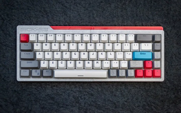
Dice Reader Brings Tech To Your Craps Game… Or, Ya Know, D&D

There are truisms about dice that you’ve probably already heard: if you have just one of them it’s called a “die”, opposite faces of each die always add up to seven, and those dots that you’re adding together are known as “pips”. But what about the infrared properties of those pips? It turns out they reflect less IR than the white body of the die and that trait can be used to build an automatic die reader.

Great projects have a way of bubbling to the surface. The proof of concept comes from way back in 2009, and while the source blog is now defunct, it’s thankfully been preserved by the Internet Archive. In recreating the project based on that barebones description, [Calvin] reached for a set of five IR transmitter/receiver pairs. Take a close look and you’ll see each transmitter is hidden under its partnered receiver. The light shines up through the receiver and the presence of the pip is detected by measuring how much of it bounces back.

This board is only the sensor portion of the design. A 595 shift register provides the ability to control which IR pair is powered, plus five more signals heading out to the analog pins of an Arduino Uno to monitor how much light is being detected by the receivers. Hey, that’s another interesting fact about dice, you only need to read five different pips to establish the value shown!

We wish there were a demo video showing this in action, but alas we couldn’t find one. We were amused to hear [Calvin] mentioned this was a sorting assignment at University and the team didn’t want to build yet another candy sorter. Look, we love an epic M&M sorter just as much as the next electronic geek, but it’s pretty hard to one-up this dice-based random number generator which rolls 1.3 million times each day.

A Look At The Basics Of Building An Arduino Watch

Miniaturization has made smart watches possible, even for the DIY maker to tinker with. For those just getting to grips with basic digital electronics, it can be daunting, however. For those just starting out, [陳亮] put together a handy guide to building the core of an Arduino-based watch.

The writeup starts at the beginning, going over the basic hardware requirements for a smart watch. This involves considering size, packaging and power draw, as well as the user interface. The build settles on an Arduino Pro Micro, as it uses the ATmega32U4 which eliminates secondary USB-to-serial chips, helping cut down on power consumption. A square IPS LCD display is used to display an analog-style watch face, and time is kept by a DS3231 real-time clock. A pair of small vibration sensors are used to wake the watch when the user moves their wrist to check the time.

While it doesn’t cover the final assembly into a watch-like form factor, it’s a handy guide on what it takes to build a working watch for those who are still getting their feet wet with hardware. Once you’ve got that down, it’s time to contemplate how you’ll build the sleek exterior. Naturally, a good maker has that covered, too.

Ping-Pong Ball Makes Great PID Example

It is a common situation in electronics to have a control loop, that is some sort of feedback that drives the input to a system such as a motor or a heater based upon a sensor to measure something like position or temperature. You’ll have a set point — whatever you want the sensor to read — and your job is to adjust the driving thing to make the sensor read the set point value. This seems easy, right? It does seem that way, but in realitythere’s a lot of nuance to doing it well and that usually involves at least some part of a PID (proportional, integral, derivative) controller. You can bog down in math trying to understand the PID but [Electronoobs] recent video shows a very simple test setup that clearly demonstrates what’s going on with an Arduino, a motor, a distance sensor, and a ping-pong ball. You can see the video below.

Imagine for a moment heating a tank of water as an example. The simple approach would be to turn on the heater and when the water reaches the setpoint, turn the heater off. The problem there is though that you will probably overshoot the target. The proportional part of a PID controller will only turn the heater fully on when the water is way under the target temperature. As the water gets closer to the right temperature, the controller will turn down the input — in this case using PWM. The closer the sensor reads to the setpoint, the lower the system will turn the heater.

Continue reading “Ping-Pong Ball Makes Great PID Example”

HDMI From Your Arduino

Creating a video signal from a computer, a job that once required significant extra hardware, is now a done deal with a typical modern microcontroller. We’ve shown you more NTSC, PAL, and VGA projects than you can shake a stick at over the years. Creating an HDMI video signal however is not so straightforward. It’s not a loosely defined analogue standard but a tightly controlled digital one upon which the clever hacks that eke full colour composite video from a single digital I/O pin will have little effect. Surely creating them from a simple microcontroller will be impossible! Not according to [techtoys], who has created an Arduino shield that creates an HDMI output from an SPI control input.

At its heart are two interesting integrated circuits that give us a little bit of insight into creating graphics at this level. First up is an RA8876 MIPI TFT controller which is a full graphics engine that produces a digital RGB output, followed by a CH7035B HDMI encoder that produces an HDMI output from the RGB. This combination of chips is particularly interesting one, because the RA8876 supports a variety of different interfaces that between them should be able to talk to most microcontrollers. In the Arduino world the only other HDMI options come via the use of an FPGA.

This is a project that seems to have been around for a couple of years, but which is still an active one. The classic Arduino shield form factor may now seem a little past its zenith, but as this board shows it’s still capable of being used for interesting new applications.

Thanks [th_in_gs] for the tip.

Tiny Game System Is An Experiment In Minimalism

Many people assumed the smartphone revolution would kill the dedicated handheld game system, and really, it’s not hard to see why. What’s the point of buying the latest Nintendo or Sony handheld when the phone you’re already carrying around with you is capable of high-definition 3D graphics and online connectivity? Software developers got the hint quickly, and as predicted, mobile gaming has absolutely exploded over the last few years.

But at the same time, we’ve noticed something of a return to the simplistic handheld systems of yore. Perhaps it’s little more than nostalgia, but small bare-bones systems like the one [Mislav Breka] has entered into the 2019 Hackaday Prize show that not everyone is satisfied with the direction modern gaming has gone in. His system is specifically designed as an experiment to build the most minimal gaming system possible.

In terms of the overall design, this ATMega328 powered system is similar to a scaled-down Arduboy. But while the visual similarities are obvious, the BOM that [Mislav] has provided seems to indicate a considerably more spartan device. Currently there doesn’t seem to be any provision for audio, nor is there a battery and the associated circuitry to charge it. As promised, there’s little here other than the bare essentials.

Unfortunately, the project is off to something of a rocky start. As [Mislav] explains in his writeup on Hackaday.io, there’s a mistake somewhere in either the board design or the component selection that’s keeping the device from accepting a firmware. He won’t have the equipment to debug the device until he returns to school, and is actively looking for volunteers who might be interested in helping him get the kinks worked out on the design.

Tea Bot Solves Another First World Problem

In the movie Wall-E, future humans live in floating chairs and have everything done for them. Today, we grumble if we have to go to physically find a light switch or a remote control. How far away can floating chairs with screens be? T2, the Tea Bot, gets us one step closer to that. Using a laser-cut frame, an ESP8266, and a servo motor, the T2 brews your tea for exactly the right amount of time.

We were kind of hoping the robot would at least dunk the tea bag in and out, but it does provide a web interface that lets you select the brew. Of course, the code is available, so you could make modifications — maybe turn on a hotplate underneath the cup.

Continue reading “Tea Bot Solves Another First World Problem”

High Precision Analog IO With Digital Pins

Reading the temperature of your environment is pretty easy right? A quick search suggests the utterly ubiquitous DHT11, which speaks a well documented protocol and has libraries for every conceivable microcontroller and platform. Plug that into your Arduino and boom, temperature (and humidity!) readings. But the simple solution doesn’t hit every need, sometimes things need to get more esoteric.

The technique summarized by an image from Microchip Appnote AN685

For years we’ve been watching [Edward]’s heroic efforts to build accessible underwater sensing hardware. When we last heard from him he was working on improving the accuracy of his Arduino’s measurements of the humble NTC thermistor. Now the goal is the same but he has an even more surprising plan, throw the ADC out entirely and sample an analog thermistor using digital IO. It’s actually a pretty simple trick based on an intuitive observation, that microcontrollers are better at measuring time than voltage. 

The basic circuit

The circuit has a minimum of four components: a reference resistor, the thermistor, and a small capacitor with discharge resistor. To sense you configure a timer to count, and an edge interrupt to capture the value in the timer when its input toggles. One sensing cycle consists of discharging the cap through the discharge resistor, enabling the timer and interrupt, then charging it through the value to measure. The value captured from the timer will be correlated to how long it took the cap to charge above the logic-high threshold when the interrupt triggers. By comparing the time to charge through the reference against the time to charge through the thermistor you can calculate their relative resistance. And by performing a few calibration cycles at different temperatures ([Edward] suggests at least 10 degrees apart) you can anchor the measurement system to real temperature.

For all the gory details, including tips for how to save every last joule of energy, check out [Edward]’s post and the Microchip appnote AN685 he references. Besides this series [Edward]’s Cave Pearl Project has already yielded an impressive number of Hackday posts. For more great hardware writeups check out a general hardware build for a single sensing node, or the “temperature sensor” [Edward] made with no external parts at all!