Some may be surprised to hear that CB radio is alive and well in the 21st century. From disaster response to operating in areas without reliable communication infrastructure, there are plenty of reasons people are still reaching for their radio and not their smartphone. Unfortunately, modern automotive interior design doesn’t have such an enlightened view. It’s hard enough to get decent cup holders in some cars, let alone a spot to hang your microphone.
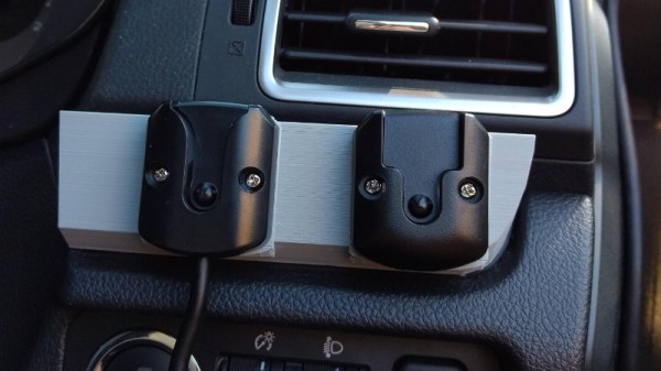
When presented with this problem in his Subaru Forester, [Alex Loizou] did what any modern hacker would, he 3D printed a mount that snaps into the stock dash. No drilling was required to attach his radio mount, it simply replaces a decorative trim piece that wasn’t doing anything anyway. Obviously this particular mount would only really work on the same year and make of vehicle as [Alex] has, but this is a good demonstration of how 3D printing can be used to adapt to existing hardware.
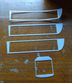 As is often the case when trying to print something to match perfectly with an existing object, there was a fair amount of trial and error required. It took a few attempts before [Alex] got the proper shape, and things weren’t made any easier by the fact he was doing his designing in TinkerCAD. While we appreciate the fact that TinkerCAD provides a web-based CAD tool that is easy enough for anyone to use, using a parametric design tool like OpenSCAD is generally preferred when you need to make slight adjustments to your model.
Software limitations aside, [Alex] managed to come up with a mount that not only holds his CB microphone, but also his handheld transmitter. All while looking about as close to stock hardware as something like this could. We especially like that he switched to a darker filament color for his final version to blend it into the dashes color scheme a bit better.
If your radio interest is a little full-fat for CB, take a look at what keeps ham radio alive and well in 2017, and if you’re a radio amateur with a hankering for the CB days we’ve got you covered.