One of the better retro historians out there on YouTube is the 8-Bit Guy, and after years of wanting to do something like this, it’s finally happening. The 8-Bit Guy is building his dream computer, heavily inspired by the Commodore 64.
Before we go into what this computer will do and what capabilities it will have, it’s important to note the 8-Bit Guy is actually doing a bit of market and user research before dedicating a year or more to this project. He’s asked other famous retrocomputing YouTubers for their input on what their ‘dream’ retrocomputer should do, and they’ve come up with a basic list of requirements. The Dream Computer will be like working on a 1957 Chevy, in that all the registers are immediately available for peeking and poking. The computer will be completely comprehensible, in so far that one person can completely understand everything, from the individual logic gates inside the CPU to the architecture of the kernel. It’ll run BASIC.
In the age of the Raspberry Pi, one might ask, ‘why not go with a Raspberry Pi?’. To the 8-Bit Guy, the Pi is just a Linux computer. Other retrocomputing projects of a similar scope to this dream computer also fail: The Mega65, a project to resurrect the Commodore 65, will be too expensive. The BASIC Engine fails because it only does composite out, and it runs on an ESP anyway, so you’re shielded from the real hardware. The same problem exists with the Maximite in that the hardware is one layer of abstraction away from the interface. The C256 Foenix is probably the closest to meeting the design goals, but it’s far too expensive, and even without the MIDI ports, SID chips, and other interesting hardware, it would still be above the desired price point.
The ‘requirement’ for this dream computer is to use only modern parts, have VGA or HDMI video out, a real CPU, preferably a 6502, use no FPGA or microcontrollers, and can run Commodore Basic. Also, this computer would cost about $50, with $100 as the absolute, maximum limit (implying a BOM cost of around $15-$25). This is absolutely, completely, astonishingly impossible. I would be deceiving you if I did not mention the impossibility of this project happening with the stated goals. This project will not meet the goal of selling for less than one hundred dollars.
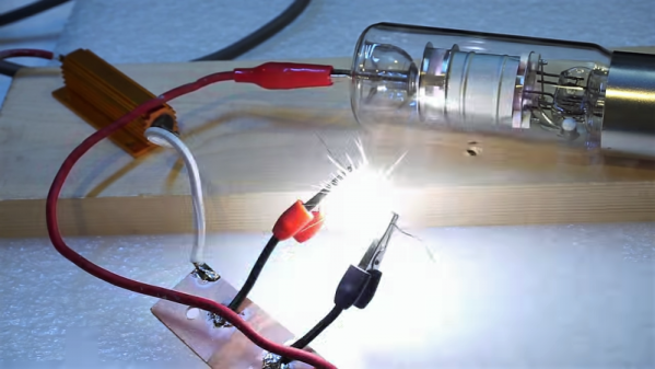
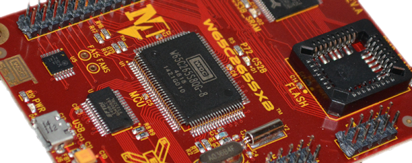
That said, there’s no harm in trying, so The 8-Bit Guy is currently working with a few dev boards, specifically one designed around the 65816 CPU. The 65816 is an interesting chip, in that it is a 6502 until you flip a bit in a register. It has a larger address space than the 6502, and everything from the World of Commodore should be (relatively) easily ported to the 65816. Why was this CPU never used in Commodore hardware? Because a Western Design Center sales guy told a Commodore engineer that Apple was using it in their next computer (the Apple IIgs). The option of Commodore ever using the ‘816 died then and there.
If you’d like to help out on this computer, there is a Facebook group for organizing the build. This Facebook group is a closed group, meaning you need a Facebook account to login. Unfortunate, but we’re looking forward to a year of updates around this dream computer. Building a computer that meets the specs is impossible, but we’re more than eager to see the community try.
Continue reading “The 8-Bit Guy Builds A 16-Bit Computer” →