How To Have A Medium Format Camera Without Breaking The Bank

For most people, experimentation with film photography comes in the form of the 35 mm format. Its ubiquity in snapshot photography means cameras are readily available at all levels, and the film offers a decent compromise between resolution and number of shots per dollar spent.

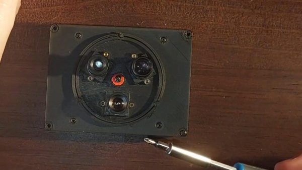
For those who wish to take their film photography further there’s the so-called medium format 120 roll film, but here opting for a higher-end camera can become expensive. Fortunately [Javier Doroteo] is here with a 3D printed medium format camera designed to use lenses intended for the Mamiya Press cameras, and from where we’re sitting it looks very nicely designed indeed.

All the files can be found on Printables along with a list of the other parts required. It’s made simple by the Mamiya lenses incorporating the shutter, but there’s still a lot of attention that has been paid to the back of the camera. This is the third version of the design and it shows, details such as the film holder and light proofing are well thought out.

Photography is so often a world in which collecting the latest kit is seen as more important than the photographs themselves, so we like and encourage camera hackers as a reaction to all that. If you’d like to see another medium format camera, this certainly isn’t the first we’ve brought you.

2025 Hackaday Component Abuse Challenge: Let The Games Begin!

In theory, all parts are ideal and do just exactly what they say on the box. In practice, everything has its limits, most components have non-ideal characteristics, and you can even turn most parts’ functionality upside down.

The Component Abuse Challenge celebrates the use of LEDs as photosensors, capacitors as microphones, and resistors as heat sources. If you’re using parts for purposes that simply aren’t on the label, or getting away with pushing them to their absolute maximum ratings or beyond, this is the contest for you.

If you committed these sins against engineering out of need, DigiKey wants to help you out. They’ve probably got the right part, and they’re providing us with three $150 gift certificates to give out to the top projects. (If you’re hacking just for fun, well, you’re still in the running.)

This is the contest where the number one rule is that you must break the rules, and the project has to work anyway. You’ve got eight weeks, until Nov 11th. Open up a project over at Hackaday.io, pull down the menu to enter in the contest, and let the parts know no mercy!

Honorable Mention Categories:

We’ve come up with a few honorable mention categories to get your ideas flowing. You don’t have to fit into one of these boxes to enter, but we’ll be picking our favorites in these four categories for a shout-out when we reveal the winners.

  • Bizarro World: There is a duality in almost every component out there. Speakers are microphones, LEDs are light sensors, and peltier coolers generate electricity. Turn the parts upside down and show us what they can do.
  • Side Effects: Most of the time, you’re sad when a part’s spec varies with temperature. Turn those lemons into lemonade, or better yet, thermometers.
  • Out of Spec: How hard can you push that MOSFET before it lets go of the magic smoke? Show us your project dancing on the edge of the abyss and surviving.
  • Junk Box Substitutions: What you really needed was an igniter coil. You used an eighth-watt resistor, and got it hot enough to catch the rocket motor on fire. Share your parts-swapping exploits with us.

Inspiration

Diodes can do nearly anything.  Their forward voltage varies with temperature, making them excellent thermometers. Even the humble LED can both glow and tell you how hot it is. And don’t get us started on the photo-diode. They are not just photocells, but radiation detectors.

Here’s a trick to double the current that a 555 timer can sink. We’d love to see other cases of 555 abuse, of course, but any other IC is fair game.

Resistors get hot. Thermochromic paint changes color with temperature. Every five years or so, we see an awesome new design. This ancient clock of [Sprite_tm]’s lays the foundation, [Daniel Valuch] takes it into the matrix, and [anneosaur] uses the effect to brighten our days.

Of course, thin traces can also be resistors, and resistors can get really hot. Check out [Carl Bujega]’s self-soldering four-layer PCB. And while magnetism is nearly magic, a broken inductor can still be put to good use as a bike chain sensor.

Or maybe you have a new twist on the absolutely classic LEDs-as-light-sensors? Just because it’s been done since the early says of [Forrest Mims] doesn’t mean we don’t want to see your take.

Get out there and show us how you can do it wrong too.

Off To The Races With ESP32 And EInk

Off to the races? Formula One races, that is. This project by [mazur8888] uses an ESP32 to keep track of the sport, and display a “live” dashboard on a 2.9″ tri-color LCD.

“Live” is in scare quotes because updates are fetched only every 30 minutes; letting the ESP32 sleep the rest of the time gives the tiny desk gadget a smaller energy footprint. Usually that’s to increase battery life, but this version of the project does not appear to be battery-powered. Here the data being fetched is about overall team rankings, upcoming races, and during a race the current occupant of the pole-position.

There’s more than just the eInk display running on the ESP32; as with many projects these days, micro-controller is being pressed into service as a web server to host a full dashboard that gives extra information as well as settings and OTA updates. The screen and dev board sit inside a conventional 3D-printed case.

Normally when talking Formula One, we’re looking into the hacks race teams make. This hack might not do anything revolutionary to track the racers, but it does show a nice use for a small e-ink module that isn’t another weather display. The project is open source under a GPL3.0 license with code and STLs available on GitHub.

Thanks to [mazur8888]. If you’ve got something on the go with an e-ink display (or anything else) send your electrophoretic hacks in to our tips line; we’d love to hear from you.

Design Scanimations In A Snap With The Right Math

Barrier-grid animations (also called scanimations) are a thing most people would recognize on sight, even if they didn’t know what they were called. Move a set of opaque strips over a pattern, and watch as different slices of that image are alternately hidden and revealed, resulting in a simple animation. The tricky part is designing the whole thing — but researchers at MIT designed FabObscura as a design tool capable not only of creating the patterned sheets, but doing so in a way that allows for complex designs.

The barrier grid need not consist of simple straight lines, and movement of the grid can just as easily be a rotation instead of a slide. The system simply takes in the desired frames, a mathematical function describing how the display should behave, and creates the necessary design automatically.

The paper (PDF) has more details, and while it is possible to make highly complex animations with this system, the more frames and the more complex the design, the more prominent the barrier grid and therefore the harder it is to see what’s going on. Still, there are some very nice results, such as the example in the image up top, which shows a coaster that can represent three different drink orders.

We recommend checking out the video (embedded below) which shows off other possibilities like a clock that looks like a hamster wheel, complete with running rodent. It’s reminiscent of this incredibly clever clock that uses a Moiré pattern (a kind of interference pattern between two elements) to reveal numerals as time passes.

We couldn’t find any online demo or repository for FabObscura, but if you know of one, please share it in the comments.

Continue reading “Design Scanimations In A Snap With The Right Math”

Estes Wants You To 3D Print Their New Model Rocket

The Estes line of flying model rockets have inspired an untold number of children and adults alike, thanks in part to their simplicity. From the design and construction of the rockets themselves to the reliability and safety of the modular solid-propellant motors, the company managed to turn actual rocket science into a family activity. If you could glue fins onto a cardboard tube and stick a plastic nosecone on the end, you were nearly ready for launch.

But what if you’re looking for something a bit more challenging? That’s where the new Estes Scorpio 3D comes in. Unlike the classic Estes kit, which included the fins, nosecone, and other miscellaneous bits of the rocket, the Scorpio kit requires you to 3D print your own parts. Do it right, and the company says you can send your creation to heights of 1,000 feet (305 m).

Continue reading “Estes Wants You To 3D Print Their New Model Rocket”

Dead Bug Timer Relay Needs No PCB

We often marvel at the many things a 555 can do. But [Zafer Yildiz] shows us that it can even take the place of a PCB. You’ll see what we mean in the video below. The timer relay circuit is built “dead bug” style with the 555 leads bent out to provide wiring terminals.

Honestly, these kinds of circuits are fun, but we would be reticent to use this type of construction for anything that had to survive in the real world. Solder joints aren’t known for being mechanically stable, so this is good for experiments, but maybe not something you want to do all the time.

Continue reading “Dead Bug Timer Relay Needs No PCB”

How Intel’s 386 Protects Itself From ESD, Latch-up And Metastability

To connect the miniature world of integrated circuits like a CPU with the outside world, a number of physical connections have to be made. Although this may seem straightforward, these I/O pads form a major risk to the chip’s functioning and integrity, in the form of electrostatic discharge (ESD), a type of short-circuit called a latch-up and metastability through factors like noise. Shielding the delicate ASIC from the cruel outside world is the task of the I/O circuitry, with [Ken Shirriff] recently taking an in-depth look at this circuity in Intel’s 386 CPU.

The 386 die, zooming in on some of the bond pad circuits. (Credit: Ken Shirriff)

The 386 has a total of 141 of these I/O pads, each connected to a pin on the packaging with a delicate golden bond wire. ESD is on the top of the list of potential risks, as a surge of high voltage can literally blow a hole in the circuitry. The protective circuit for this can be seen in the above die shot, with its clamping diodes, current-limiting resistor and a third diode.

Latch-up is the second major issue, caused by the inadvertent creation of parasitic structures underneath the P- and NMOS transistors. These parasitic transistors are normally inactive, but if activated they can cause latch-up which best case causes a momentary failure, but worst case melts a part of the chip due to high currents.

To prevent I/O pads from triggering latch-up, the 386 implements ‘guard rings’ that should block unwanted current flow. Finally there is metastability, which as the name suggests isn’t necessarily harmful, but can seriously mess with the operation of the chip which expects clean binary signals. On the 386 two flip-flops per I/O pad are used to mostly resolve this.

Although the 386’s 1985-era circuitry was very chonky by today’s standards, it was still no match for these external influences, making it clear just how important these protective measures are for today’s ASICs with much smaller feature sizes.