Bus Sniffing Leads To New Display For Vintage Casio

Despite his best efforts to repair the LCD on his Casio FX-702P, it soon became clear to [Andrew Menadue] that it was a dead-end. Rather than toss this relatively valuable device in the trash, he wondered if would be possible to replace the LCD with a more modern display. Knowing that reverse engineering the LCD panel itself would be quite a challenge, he decided instead to focus his efforts on decoding the communications between the calculator’s processor and display controller.

With his logic analyzer connected to the Casio’s four bit bus [Andrew] was able to capture a sequence of bytes during startup that looked promising, although it didn’t quite make sense at first. He had to reverse the order of each nibble, pair them back up into bytes, and then consult the FX-702P’s character map as the device doesn’t use ASCII. This allowed him to decode the message “READY”, and proved the concept was viable.

Of course a calculator with a logic analyzer permanently attached to it isn’t exactly ideal, so he started work on something a bit more compact. Armed with plenty of display controller data dumps, [Andrew] wrote some code for a STM32 “Blue Pill” ARM Cortex M3 microcontroller that would sniff and decode the data in near real-time. In the video after the break you can see there’s a slight delay between when he pushes a button and when the corresponding character comes up on the LCD below, but it’s certainly usable.

Unfortunately, the hardware he’s created for this hack is just slightly too large to fit inside the calculator proper. The new LCD is also nowhere near the size and shape that would be required to replace the original one. But none of that really matters. While [Andrew] says he could certainly make the electronics smaller, the goal was never to restore the calculator to like-new condition. Sometimes it’s more about the journey than the destination.

Continue reading “Bus Sniffing Leads To New Display For Vintage Casio”

Gorgeous Clock, And Not A Line Of Code In Sight

[Harry] dropped us a note to let us know about his completed CMOS clock project, and we’re delighted that he did because it’s gorgeous. It’s a digital clock satisfyingly assembled entirely from hardware logic, without a single line of code. There are three main parts to this kind of digital clock: ensuring a stable time base, allowing for setting the time, and turning the counter outputs into a numerical display.

Keeping accurate time is done with a 32.768 kHz crystal, and using CMOS logic to divide that down to a 1 Hz square wave. From there, keeping track of hours and minutes and seconds is mostly a matter of having counters reset and carry at the appropriate times. Setting the clock is done by diverting the 1 Hz signal so that it directly increments either the hours or minutes counter. The counter values are always shown “live” on six 7-segment displays, which makes it all human-readable.

The whole thing is tastefully enclosed in a glass dome which looks great, but [Harry] helpfully warns prospective makers that such things have an unfortunate side effect of being a fingerprint magnet. Schematics and design files are provided for those who want a closer look.

This clock uses a crystal and divider, but there’s another method for keeping accurate time and that’s to base it off the alternating current frequency of power from the grid. Not a bad method, albeit one that depends on being plugged into the wall.

Wire Wrapping Skills Put To Use For Sign Making

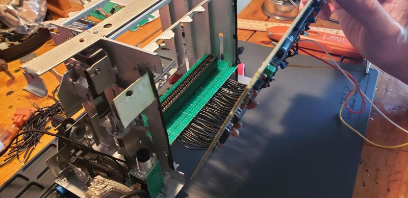
We don’t see many wire wrapped circuits these days, and you could be forgiven for thinking it was nearly a lost art at this point. But that doesn’t mean the technique can’t be applied elsewhere. [MiHu-Works] recently wrote in to share a sign they recently made for a client’s restaurant that looks an awful lot like the back panel of a homebrew computer to us.

Before you get a chance to scroll down and complain about it in the comments, we admit this one is fairly deep into the crafts side of the spectrum. But it’s also a gorgeous piece that we’d be happy to hang up in the hackerspace, so we don’t care. There might not be any angry pixies zipping around through all that lovingly wrapped copper wire, but it certainly feels like you’re looking at the internals of some complex machine.

To make it, [MiHu-Works] first printed out the lettering on paper and put it on the wood to serve as a guide. Roofing nails were then driven into the wood to create the outline of the text. A simple tool made from a forked piece of wood was placed under the head of each nail as it was hammered in to make sure the depth was consistent. It also made sure there was adequate room underneath to wrap the copper wires through them. Then it was time for the wrapping…so much wrapping. (Who is going to come through with the robot to do this?)

A few years back we asked the Hackaday readers if they thought the days of wire wrapped circuits were over. It generated a lot of discussion and interesting ideas, but looking at projects like this, perhaps we were asking the wrong question.

Continue reading “Wire Wrapping Skills Put To Use For Sign Making”

DIY Large Format Book Press Puts On The Pressure

For those in the audience who aren’t well versed in wrangling dead trees, a large press with a lot of clamping pressure can be used for binding books or printing. It can even be used to squeeze the water out of homemade paper. It’s an important tool for anyone looking to make or repair books, but they also tend to be fairly expensive. Which is why [Paul] decided to make his own.

Despite the preconceived notions you might have about the type of guy who binds his own books, it seems like [Paul] is a rather modern fellow. He actually designed the press in CAD and made many of the parts for it on his CNC router. That’s not strictly required, though we do think cutting out the hole for the monstrous lead screw nut would be a bit tricky if you had to do it by hand. But beyond that, the design is pretty straightforward and the video after the break provides a very clear step-by-step guide on how to build your own.

In the past we’ve seen how a similar, if much smaller, book press can be used to make bound books of all those PDFs littering your computer. These sort of projects are getting more rare in an increasingly paperless world, but we always like to see people keeping the old ways alive. If the revolution comes and we end up needing to publish Hackaday on hand-pressed paper, we’ll know who to call.

Continue reading “DIY Large Format Book Press Puts On The Pressure”

Nixies Adorn A Cold War Relic To Make A Geiger Clock

Say what you will about the centrally planned economies of the Soviet bloc during the Cold War, but their designs had a brutal style all their own. When one comes across an artifact from that time, like a defunct Polish Geiger counter from 1971, one celebrates that style the only way possible: by sticking Nixies tubes on it and making it into a Geiger clock.

Right off the hop, we’ve got to say that we’re in love with the look of [Tom Sparrow]’s build. And we’ll further stipulate that most of the charm comes from the attractive Bakelite case of the original Geiger counter. This looks like the real deal, with the marbleized look presumably caused by different color resins mixing in the mold. [Tom] did an admirable job bringing back the original shine with some polish and elbow grease; no doubt the decades had taken their toll on the original shine. The meter was gutted to make room for the clockworks, which is an off-the-shelf Nixie module. The tubes stick through holes drilled in the top; a pair of LEDs adorn the front panel and an incandescent bulb provides a warm glow behind the original meter. Combined with the original rotary switch and labels, the whole thing has a great look that’s perfect for a desk.

We’ve featured a lot of retro-classic Nixie builds, from digitizing a 1940s radio to a 1970s multimeter turned into a dice-roller. As for Nixie clocks, we’re just glad to take a break from the Nixie steampunk trend for a bit.

[via Dangerous Prototypes]

Why Some Chips Have Inconvenient Pinouts

If you’ve ever handled a chip with a really strange or highly inconvenient pinout and suspected that the reason had something to do with the inner workings, you may be interested to see [electronupdate]’s analysis of why the 4017 Decade Counter IC has such a weirdly nonintuitive pinout. It peeks into an IC design dating from the 1970s to see an example of the kind of design issues that can affect physical layout.

Inside the 4017. Want to make sense of how lines and shapes on a silicon wafer make an IC work? With the right teachers, it’s simple.

In the case of the 4017, once decapped and the inner workings exposed, things became more clear. Inside the chip are a bunch of flip-flops and NAND gates, laid out in a single layer. Some of the outputs (outputs 5 and 1 for example, physically on pins 1 and 2 respectively) share the same flip-flop.

The original design placed the elements in a way that made the most logical sense for routing and layout, which resulted in nice and tidy inner workings but an apparently illogical pinout. A lot of this is probably feeling familiar to anyone who has designed and routed a single-layer PCB, where being limited to one layer makes it important to get the most connections as directly near one another as possible.

Chip design has of course come a long way since the 70s, but there is forever some level of trade-off to be made between outward tidiness and inner design harmony. The next time you’re looking at a part with an apparently illogical pinout, there’s a fair chance it makes far more sense on the inside.

If any of you are interested in decapping ICs yourselves to see what’s inside, we saw that it’s possible with commonly available chemicals, not just nasty ones.

Continue reading “Why Some Chips Have Inconvenient Pinouts”

Concrete Solder Squid Is A Solid Solution

Although it’s possible to buy a soldering setup out of the box, the one that works for you will likely develop over time. Honestly, it may never stop evolving. Sure, you can start with el-cheapo helping hands or a nice hobby vise, but it probably won’t end there. Why? Because no one of these tools will be right for all applications, unless you plan to solder the same thing over and over again. Sometimes it’s just easier to alligator clip a board in place than to slowly manipulate the jaws of a vise, but those helping hands have such a limited range of motion.

Have you been meaning to build a soldering squid out of coolant hose because that stuff just looks so dang cool and bendy? Well, then let Hackaday alum [JeremySCook] show you how it can be done. A few years ago he built a similar squid with a wooden base, but it just isn’t heavy enough, so he redesigned it with a concrete base. He took the opportunity to make some nice tweaks, like zip-tying a small PC fan and 9 V to make an endlessly repositionable ventilation system, and adding a big clip in the back for extra stability while soldering. And of course, threading the solder spool on to one of the hoses is genius.

If you follow [Jeremy] at all, you know he’s been playing around with concrete for a while now, and it’s neat to see him cement his devotion to the stuff by using it in the pursuit of better tools. He’s got the files for the printed mold up on GitHub, and the build video after the break should be all set up by now.

Not custom enough for you? Fire up that printer and make your own ball and socket arms.
Continue reading “Concrete Solder Squid Is A Solid Solution”