As with anything else, once your knowledge of coffee expands, the more attractive it becomes to control as much of the process as possible. Buying whole beans and grinding them at home is one thing, but you’re not a real coffee geek unless you’re buying big bags of green beans and roasting them yourself in small batches.
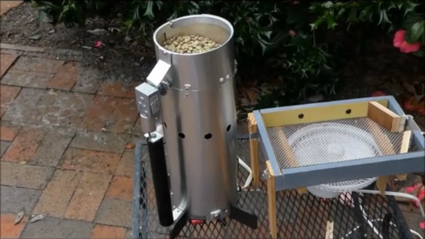
[Larry Cotton] has made an even more portable version of the wobble disk roaster we saw last summer. Beneath the housing made of aluminium flashing is the guts of a $15 Harbor Freight heat gun pointing upward at a metal strainer. A large metal disk mounted at a 45-degree angle to the spinning axis tosses and turns the beans as they get blasted with heat from below. [Larry] used a 12 VDC motor to run the wobble disk, and an an adapter to change the heat gun from 120 VAC to 12 VDC. This baby roasts 1½ cups of beans to city plus (medium) level in 12-15 minutes. Grab a cup of coffee and check it out after the break.
Roasting beans isn’t rocket science. Even so, there are some things you would benefit from knowing first, so here’s our own [Elliot Williams] on the subject of building DIY roasters.
Continue reading “How To Cobble A Wobble Disk Roaster Together”
 Our colleague [Tom Nardi] has the solution for his cyberdeck though, in the form of