Robot Makes Literal Daisy Chains

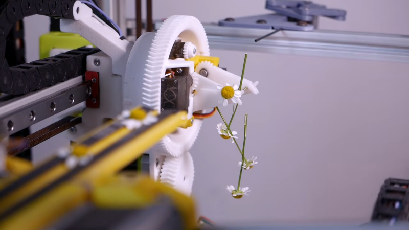
[Jude Robinson]’s robot Daisy has an unusual function: making a literal chain of daisies. The device is his student final project and demonstrates how a system can replace sensing with clever mechanical constraints. Instead of bringing tools to bear on each daisy, the daisies are brought to the tools in a repeatable, deterministic way.
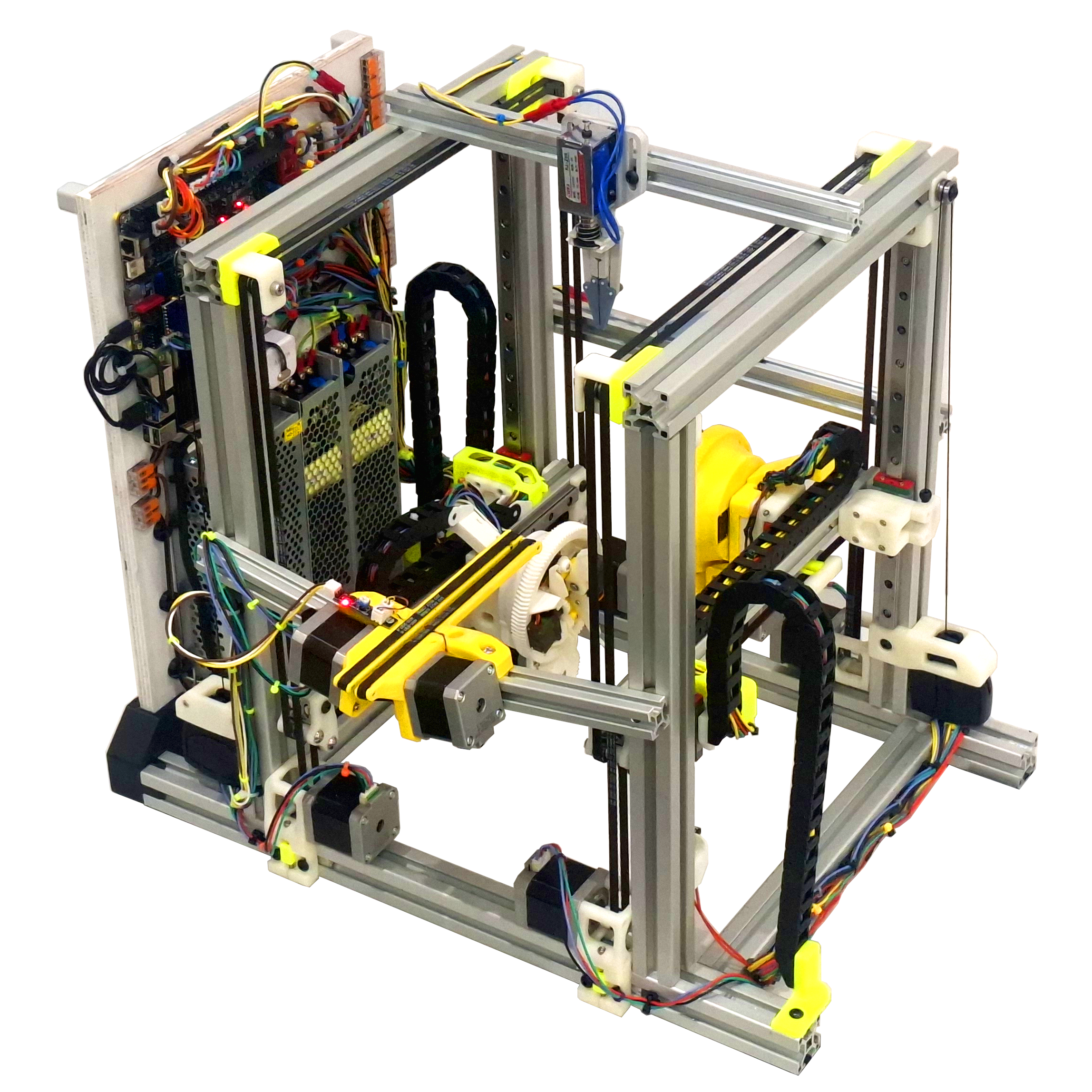
Daisy is essentially two X-Y gantries with grippers facing one another. Between them is a conveyor upon which daisies are fed, plus a blade at the top with a threading post nearby. A gripper takes a daisy, feeds the stem through the hole in the previous one, then lifts the new addition up to a scalpel blade which cuts a short incision. The thin threading post goes through the new hole in the new stem, ready for the next daisy to be inserted. The two gantries alternate roles, building the chain one daisy link at a time.

[Jude] says that daisy stem shape and diameter have the most impact on reliability, so it’s very important to constrain the daisies such that the scalpel and threading operations work reliably. This is primarily done with v-shaped profiles in the grippers which automatically center stems of different sizes. The sheath around the scalpel blade also plays a role in constraining and supporting the stems as they are gently pierced and sliced. Tuning these elements was a big part of making the system work.

Watch it in action in the video (embedded below) which shows how clever mechanical design can turn an uncertain problem — like how to handle daisies of different sizes — into a deterministic one with the help of clever mechanical design. That same concept is at work in everything from simple nut sorters to highly complex paper airplane machines.
Continue reading “Robot Makes Literal Daisy Chains” →

What Are Your Indispensable Software Skills?

Using tools properly takes skill, and this goes for software tools as well as hardware. You don’t just buy a paintbrush and on day one paint the Mona Lisa. Similarly, you can’t just open up a CAD program and whip out whatever 3D objects your heart desires, or fire up Vim and start typing. Software tools take a bit of learning before you can wield them efficiently, if even at all. And because you can’t be skilled at everything, no matter how hard we are all trying, it’s good to have at least some of the software tools you know do double duty.

Tom and I were watching [Clough42] design an electronics cabinet for a CNC machine. He does a lot of CNC machining and design work, so he’s no stranger to CAD software. So he downloaded all of the parts that he needed inside cabinet, slid them onto virtual DIN rails, modeled the hinges, and made sure that everything fit before buying anything.

Now I know that some of you out there do CAD modeling like this all the time, but for Tom and I, who are 3D printerers and PCB layouterers, doing the CAD without then following through and finishing up with the CAM seemed a bit novel. I never open CAD unless I’m going to have a machine make the thing – otherwise I’d just draw it out on paper, right? But [Clough42]’s point is that getting models of all of the subparts is so easy these days, you might as well model it.

If, and this is the big “if”, you know your way around the CAD tool of your choice. If you don’t yet, it’s going to be a couple of days’ worth of effort to get there. But once you reach CAD nirvana, you’ll find it’s useful for sketching up anything that has a third dimension to it, not just stuff you need to print out.

What other software tools are like CAD in that once you know them well enough, a wealth of applications opens up before you? Of was this just an instance of having a hammer and everything looking like a nail?

Motorized Planer Height Adjustment Dials In

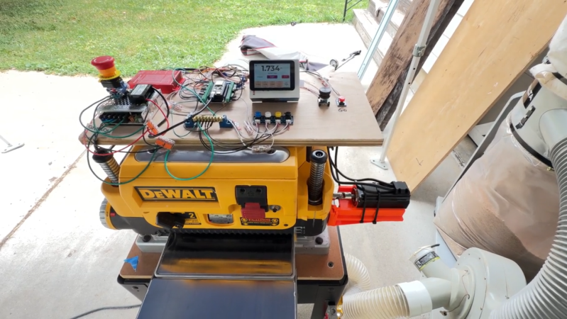
Having access to a planer opens up a lot of options for woodworking. It enables a craftsman to work with much rougher lumber and the finished results generally have tighter tolerances. But as [DendroLabsDev] found out, the height adjustment wheel on a planer needs a lot of turns to go from its lowest to highest position, and this gets tiresome when greasing parts during maintenance. So what started as a quick hack to quickly perform this single maintenance task eventually resulted in this programmable height adjustment that’s in use on the planer full-time now.

The motor attached to the height adjustment for the planer is a stepper motor, capable of around 1000 steps per inch. Since revolutions on this tool with the stock wheel adjust only a small amount per revolution, this can in theory enable very small tolerances to be dialed in consistently. Not only that, but [DendroLabsDev] has programmed it with a few different modes, the first of which allows a board to be planed to a certain thickness by making several passes, mimicking the workflow of a human-controlled machine. Then a device to zero the position was added, and then the ability to save the height adjustments to make replication across different boards was added, and then a mode to step through set amounts per pass.

What [DendroLabsDev] has essentially made is a high-dollar planer control that is actually available in the most expensive planers, but adapted for a DeWalt planer easily available and semi-affordable at many local hardware stores. It is also theoretically adaptable for any planer with an adjustment wheel, and [DendroLabsDev] has some plans to improve the control system and package it with a PCB and enclosure that would allow it to be a more accessible product for other woodworkers. Adding electronics to woodworking tools other than routers is a popular pastime, take this CNC-controlled scroll saw for example.

Delta Pen Plotter Draws In Multiple Colors

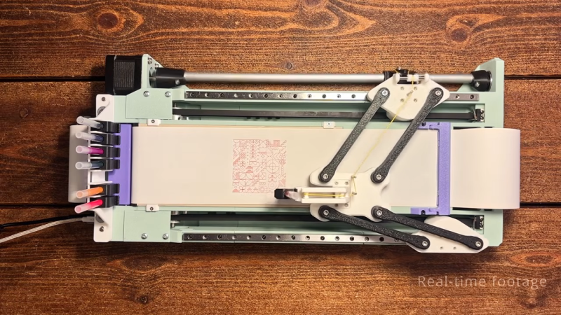
If you’re building your first plotter, or you just like thinking in right angles, you’d probably consider a Cartesian design for your build. [András Vujovits] went another route with his project, building an impressive delta pen plotter with a useful tool changer, to boot.

The build relies on a unique motion system, wherein two NEMA 17 stepper motors drive either side of the linkage to control the position of the end effector—in this case, a pen carriage. By controlling the position of each side of the mechanism, it’s possible to move the pen through XY space. Running the show is an Arduino Nano, fitted with a GRBL shield and appropriate stepper motor drivers.

The magnetic tool changer is particularly nifty, too. It allows the plotter to grab a different ink at will to add more color to the drawing. It’s well-designed, with the plotter able to change inks without losing accuracy or otherwise fumbling the switchover. The plotter uses Muji ball point pens, which are available in a range of colors and draw with slick, clean lines. It’s also quite a fast plotter, thanks in part to [András]’s efforts to keep the pen carriage light by using a smart mechanism to offload the pen lifting actuator to the main body.

[András] has plans available, but you’re going to have to pay for them. Still, it’s always nice to see a new machine in the wild. Video after the break.

Continue reading “Delta Pen Plotter Draws In Multiple Colors” →

Wooden Piano Keys Hold Your Less-Wooden, Not-Piano Keys

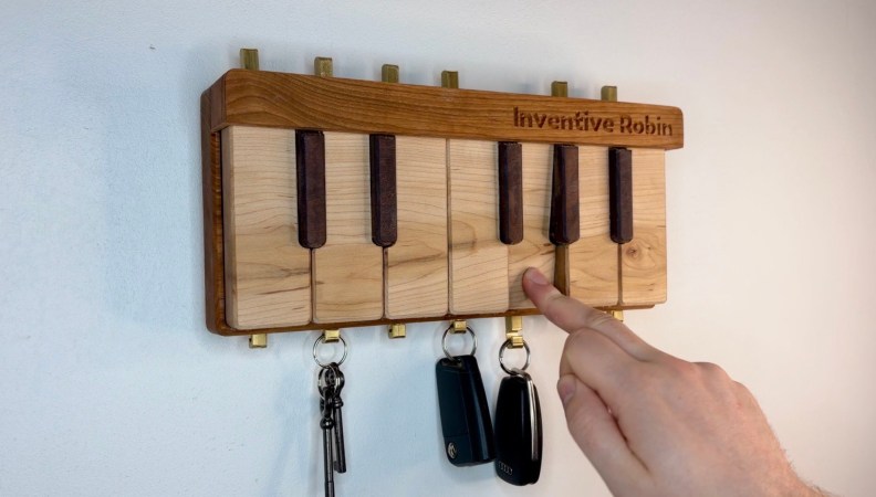
There are many ways to deal with keys: a bowl next to the entryway, a junk drawer, or you can just leave them in your pockets and hope you remember to check on Laundry Day. [Inventive Robin] has come up with his own, unique take on the key holder concept: he’s got piano keys to hold his car keys, CNC’d out of some nice hardwoods.

Of course, it’s not just a fake one-octave piano with hooks glued to it; that wouldn’t be quite enough to catch our fancy. There’s a mechanism hidden under the “white” keys– made of maple– that lowers the brass hooks when you press the, er, wooden actuator, so you can retrieve your, uh, lock-openers. Keys, that is. They’re both keys, of different sorts, because English is a wonderful language. In any case, pressing the maple key a second time lifts the brass hook, trapping the likely metal key hanging on it.

The mechanism was carved from acetyl sheet on the same Shapoko CNC machine that handled the wood, and was assembled with purchased metal rods, springs, and some plastic standoffs. It’s very satisfying to watch it work unenclosed, so check out the build video embedded below to see that in action– jump to 4:46 if you don’t want to get the whole design brief.

It’s not the most complex of hacks, but it’s beautifully done inside and out, and [Robin] is clearly happy with the result. It’s nice enough that visitors might want to photograph the key holder, but perhaps have them do it sans keys– those photos could potentially be a security risk.

Continue reading “Wooden Piano Keys Hold Your Less-Wooden, Not-Piano Keys” →

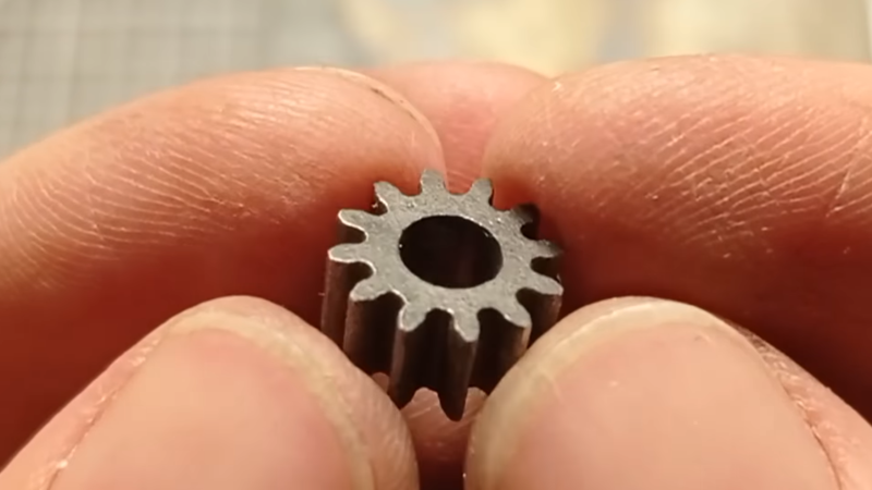
A fine steel gear is shown held between a man's fingertips.

Cutting Steel Gears With Homemade EDM

Electric discharge machining (EDM) may be slower than alternatives like laser cutting, water jets, or a milling machine, but for some applications there’s no alternative: it can cut through any conductive material, no matter how hard, and it leaves no mechanical or thermal stress in the workpiece. Best of all, they’re relatively accessible for a resourceful hacker, such as [Inofid], who recently built the second iteration of his desktop wire EDM.

The EDM’s motion system comes from a cheap desktop CNC router, which had a water tank mounted in its workspace and had the spindle replaced with a wire-management mechanism. The wire-management mechanism needs to continuously wind a tensioned brass wire from one spool through the cutting zone onto another spool. The tensioning system uses two motors: one to pull the wire through, and one to maintain tension by slightly counteracting it, with a tension sensor and Ardunio to maintain the proper tension. If it detects that the wire has broken, it can stop the CNC controller. To keep the wire from breaking or short-circuiting with the workpiece, a current monitor counts sparks between the wire and workpiece and uses this to predict whether the wire is getting too close to the metal, in which case it slows down the movement.

As a first test, [Inofid] cut through a five by three centimeters-thick block of aluminium, taking two hours but producing a clean cut. To speed up the next cut, [Inofid] added a pump and filter to remove sludge from the cutting area. The next cut was an aluminium gear, and then a meshing steel gear, which took about ten hours but turned out well.

EDMs of various kinds appear here from time to time, particularly since the popularization of 3D printers. We’ve even seen one built into a lathe.

Thanks to [Keith Olson] for the tip!

The Threadless Ball Screw Never Took Off, But Don’t Write It Off

If you’ve never heard of the threadless ball screw, which was invented over sixty years ago, [Angus] of Maker’s Muse has a video demonstrating the whole thing, covering its history and showcasing both its strengths and weaknesses. If you like seeing mechanical assemblies in action, give it a watch.

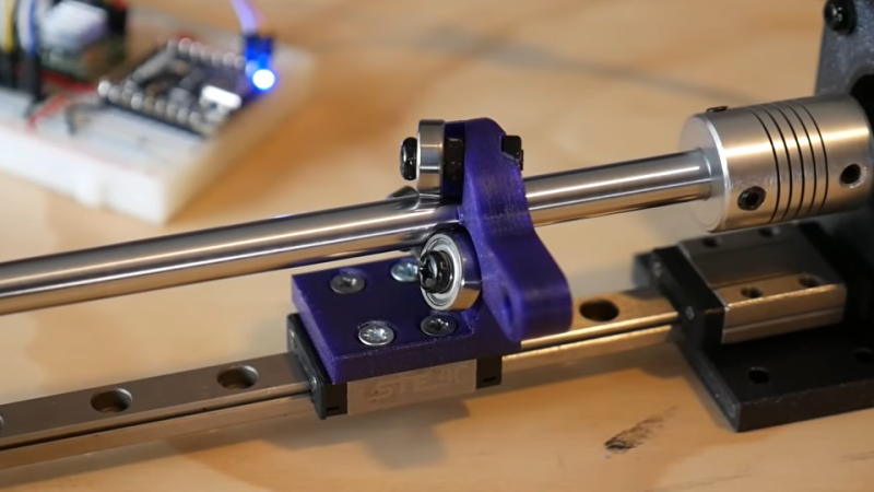
The device — consisting of little more than a smooth rod and three angled ball bearings — is a way to turn rotational motion into linear motion. Not a single belt, thread, or complex mechanical assembly in sight. While a simple nut on a threaded rod can turn rotation into linear motion, those come with their own issues. The threadless ball screw was one effort at finding a better way.

While it lacks precision, the threadless ball screw nevertheless offers quiet and smooth motion with adjustable tension in a very DIY-friendly design.

Threadless ball screws never really took off, although they were given some consideration for use in 3D printers back in the RepRap days. Today one can purchase quality CNC components without leaving one’s web browser, but back in the early 2000s things like lead screws and ball screws were rather more specialized, less accessible, and more expensive than they are today. RepRap folks had to make their own solutions. But while the threadless ball screw is a very DIY-friendly design, it was ultimately lacking in performance.

The main problem is they’re just not precise enough for anything like CNC work. [Angus] does some back-and-forth tests with a 3D printed unit that shows serious drift after only a few minutes. Now, he knows perfectly well that his 3D-printed test unit is far from ideal, but the rapidity at which it drifted was still a surprise. Making a carriage with two threadless ball screws — one at each end — performed a lot better, but was ultimately still flawed.

It’s not all bad. There’s zero backlash. They are mechanically simple, remarkably smooth, and utterly quiet. Also, [Angus] discovered that the maximum force this setup can be made to apply is surprisingly significant, and is directly related to the tension on the bearings. That means one can trivially adjust how easily the carriage slips  (or doesn’t) just by tightening or loosening the screw holding each bearing.

Sure, they’re not precise. But maybe you don’t need precision. Maybe you just need to move something back and forth in a strong & silent sort of way that can still slip gracefully (and quietly) if something goes awry, like bottoming out an axis. 3D printing makes it pretty easy to whip one up, so maybe there’s still a place for the threadless ball screw.

Continue reading “The Threadless Ball Screw Never Took Off, But Don’t Write It Off” →