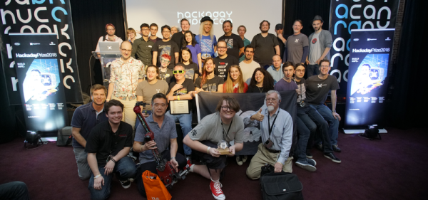
Dexter, an open-source, high-precision, trainable robotic arm has just been named the Grand Prize winner of the 2018 Hackaday Prize. The award for claiming the top place in this nine-month global engineering initiative is $50,000. Four other top winners were also named during this evening’s Hackaday Prize Ceremony, held during the Hackaday Superconference in Pasadena, California.
This year’s Hackaday Prize featured challenges with five different themes. Entrants were asked to show their greatest Open Hardware Design, to build a Robotics Module, to design a Power Harvesting Module, to envision a Human Computer Interface, or to invent a new Musical Instrument. Out of 100 finalists, the top five are covered below. Over $200,000 in cash prizes have been distributed as part of this year’s initiative where thousands of hardware hackers, makers and artists compete to build a better future.

Dexter is the Grand Prize winner of the 2018 Hackaday Prize. This remarkable robotic arm design brings many aspects of high-end automation to an open source design which you can utilize and adapt for your own needs. In addition to impressive precision, the design is trainable — you can move the joints of the arm and record the motion for playback.
The image here shows position data from one arm being moved by a human, controlling another arm in real time. Each joint utilizes a clever encoder design made up of a wheel with openings for UV sensors. Sensing is more than merely “on/off”. It tracks the change in light intensity through each opening for even greater granularity. The parallel nature of an FPGA is used to process this positioning data in real time.
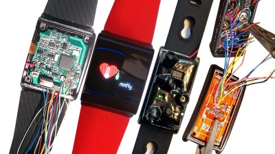
Manufacturing custom electronics is a tricky, costly, and time-consuming process. What if you could sidestep most of that by starting with a powerful, proven consumer good that is modified to your specifications? This project takes existing fitness trackers and customizes the hardware and software to become sensor suites for mental health research. Dig into this one and see how they can help patients become aware of unconscious behaviors (like trichotillomania which is compulsive hair pulling) and change them over time.

This project focuses on an alternative power source for times when traditional infrastructure is not functioning or simply not available. You may be familiar with generators made using DC motors. The Portal Point Generator replicates that simplicity, but goes beyond with instructions for building the generator itself for far greater efficiency. A winding jig is used to make the coils which are placed inside of the 3D printed generator parts along with permanent magnets to complete the build. Here you can see it in testing as a wind generator in Antarctica, but it is easily adapted to other applications like using water wheels.
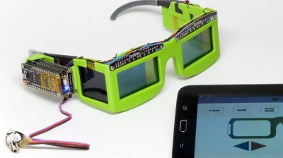
There is a body of research that suggest a link between cardiac cycle and anxiety-producing visuals; you may have a different emotional reaction to the things you see based on what part of a heartbeat is occurring when your brain process information from your eyes. This could have profound implications in areas like PTSD research. EmotiGlass uses LCD screens to selectively block the wearer’s vision. This can be synchronized with heat beat, avoiding the instant where a negative emotional response is most likely. Think of them as 3D shutter glasses for mental health research.
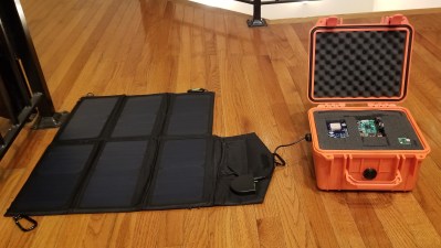
Recovering from natural disasters is an enormous challenge. The infrastructure that supports the community is no longer in place and traditional communications simply cease to exist. PR-Holonet was inspired by the recovery process after hurricanes in Puerto Rico. It leverages the availability of commercial electronics, solar power sources, and enclosures to build a communications system that can be deployed and operated without the need for specialized training. Once in place, local devices using WiFi can utilize text-based communications transferred via satellite.
Congratulations to all who entered the 2018 Hackaday Prize. Taking time to apply your skill and experience to making the world better is a noble pursuit. It doesn’t end with the awarding of a prize. We have the ability to change lives by supporting one another, improving on great ideas, and sharing the calling to Build Something that Matters.
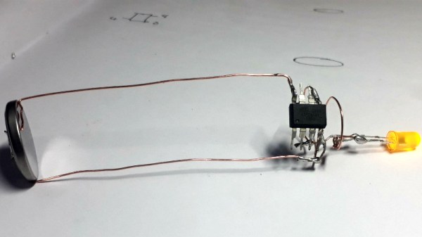
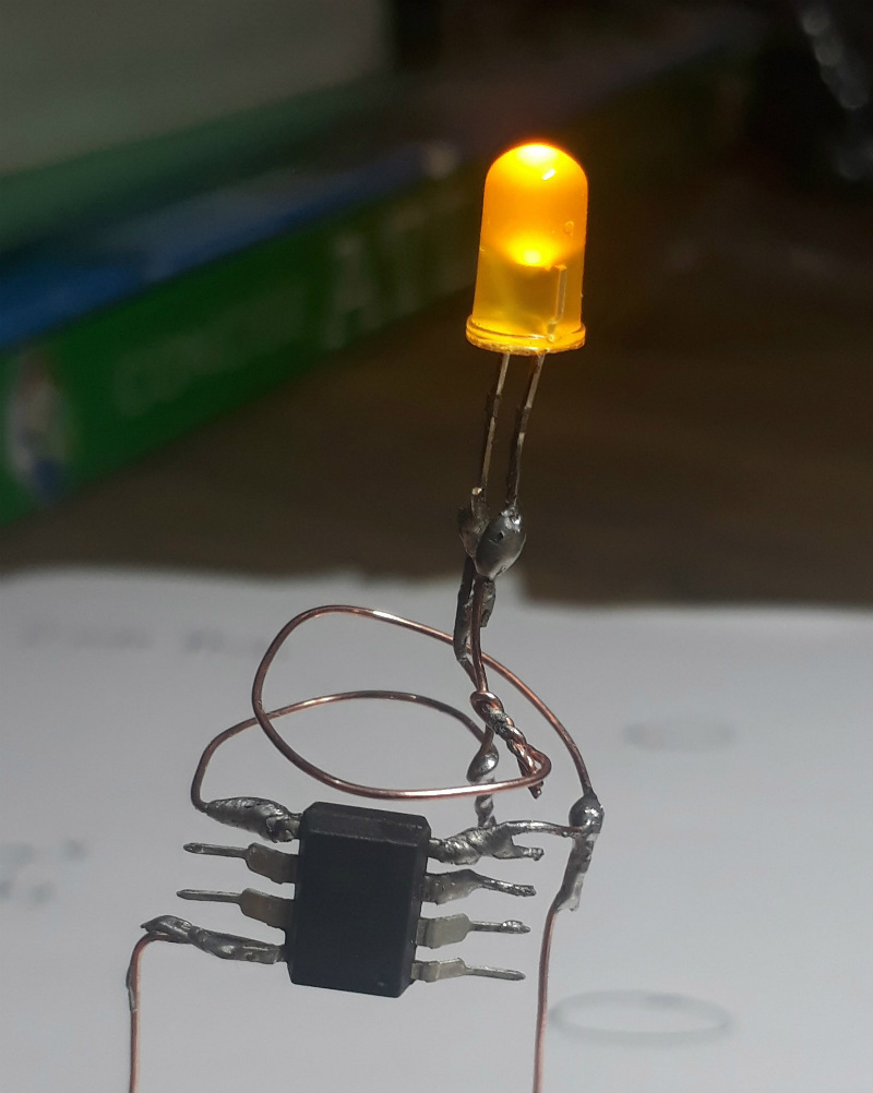 To give the LED a fading effect, [Amal] uses a ATtiny85 programmed with the Arduino IDE. His code uses the


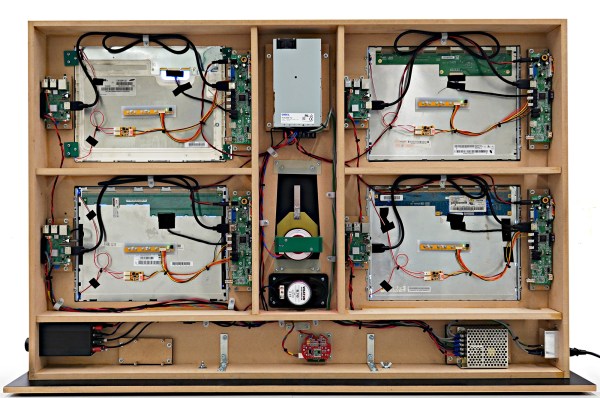


The red round board at the bottom is the PIR motion sensor, the part of another project which is not related neither to HAL nor to the badge. There is a clearly visible 915 MHz module, which is disconnected and has no function in this project.
It is connected to the lower left Raspberry just because it has to be supplied with about 3V and it uses Raspberry’s LDO. It also generates Reset signal for all four Raspis, as it turned out that the 5V supply (bottom right) delivers the slow-rise voltage when turned on, so Raspis won’t boot at all without the external Reset.
When someone walks in front of HAL, motion sensor randomly triggers one of 30 HAL’s sentences from the movie. That’s why the lower left Raspberry is connected to the amplifier and has an extra wire from the motion sensor board to GPIO 24.