
Whether or not you chose to believe our claim that we planned it this way, the holidays happen to fall right smack in the middle of our ongoing Circuit Sculpture Contest, which challenges hackers to build circuits that double as bona fide works of art. It’s become almost too easy to spin up your own PCB, so why not try your hand at building in three dimensions and without a net? The holidays are a perfect time for it as it’s not only a reprieve from the work, school, or forced labor camp that usually ties up our waking hours, but can also be a source of inspiration.
 Case in point, this festive LED Christmas tree entry that comes our way courtesy of [Vincent Mkes]. This one really has it all: a recognizable theme, fantastic wire work, copious amounts of LEDs, and in a touch that is sure to delight even the electronics Scrooges amongst our readership, he does it all with the venerable 555 timer. It’s really what the Circuit Sculpture Contest is all about: taking a circuit that might otherwise be pretty ordinary and turning it into something truly unique.
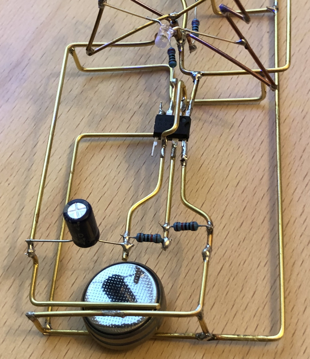
The astute Hackaday reader (as if there was any other type) will likely notice there are actually two NE555 timers under the tree, each blinking their respective bank of LEDs at a different frequency. This makes the final result a bit more vibrant, and through some last-minute revisions, [Vincent] was able to hook them both up to a single power supply to really capture the minimalist spirit of the Contest.
As an early Christmas gift to us all, [Vincent] has done an excellent job documenting this build so anyone who wishes to infuse their end of year party with a little diode-driven holiday cheer can follow along. He’s included build instructions as well as diagrams of the circuit, though we encourage anyone looking to make one of their own to experiment a bit and put their own spin on it. After all, this is supposed to be art.
There’s still plenty of time to get your own entry into the Circuit Sculpture Contest, Yule-related or otherwise. Just document your build on Hackaday.io and submit it before the January 8th, 2019 deadline. Remember that entries can’t just look cool, they still need to be functional. Words to live by in general, but doubly important when they’re the rules of a contest.


The red round board at the bottom is the PIR motion sensor, the part of another project which is not related neither to HAL nor to the badge. There is a clearly visible 915 MHz module, which is disconnected and has no function in this project.
It is connected to the lower left Raspberry just because it has to be supplied with about 3V and it uses Raspberry’s LDO. It also generates Reset signal for all four Raspis, as it turned out that the 5V supply (bottom right) delivers the slow-rise voltage when turned on, so Raspis won’t boot at all without the external Reset.
When someone walks in front of HAL, motion sensor randomly triggers one of 30 HAL’s sentences from the movie. That’s why the lower left Raspberry is connected to the amplifier and has an extra wire from the motion sensor board to GPIO 24.