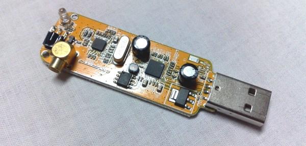
Hackaday Dictionary: Software Defined Radio (SDR)

We are entering a new era of radio technology. A new approach to building radios has made devices like multi-band cell phones and the ubiquitous USB TV receivers that seamlessly flit from frequency to frequency possible. That technology is Software Defined Radio, or SDR.

A idealized radio involves a series of stages. Firstly, an antenna receives the radio signal, converting it into an electrical signal. This signal is fed into a tuned resonator which is tuned to a particular frequency. This amplifies the desired signal, which is then sent to a demodulator, a device which extracts the required information from the carrier signal. In a simple radio, this would be the audio signal that was encoded by the transmitter. Finally, this signal is output, usually to a speaker or headphones.
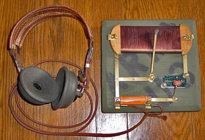
A replica foxhole crystal set. Photo: Bill Jackson

That’s how your basic crystal radio works: more sophisticated radios will add features like filters that remove unwanted frequencies or additional stages that will process the signal to create the output that you want. In an FM radio, for example, you would have a stage after the demodulator that detects if the signal is a stereo one, and separates the two stereo signals if so.

To change the frequency that this radio receives, you have to change the frequency that the resonator is tuned to. That could mean moving a wire on a crystal, or turning a knob that controls a variable capacitor, but there has to be a physical change in the circuit. The same is true of the additional mixing stages that refine the signal. These circuits may be embedded deeply in the guts of the radio, but they are still there. This is the limitation with normal receivers: the radio can’t receive a signal that is outside the range that the resonator circuit can tune to, or change the way it is demodulated and processed. If you want to receive multiple frequency bands or different types of signals, you need to have separate pathways for each band or type of signal, physically switching the signal between them. That’s why you have physical AM/FM switches on radios: they switch the signal from an AM radio processing path to an FM one.

Software Defined Radios remove that requirement. In these, the resonator and demodulator parts of the radio are replaced by computerized circuits, such as analog to digital converters (ADCs) and algorithms that extract the signal from the stream of data that the ADCs capture. They can change frequencies by simply changing the algorithm to look for another frequency: there is no need for a physical change in the circuit itself. So, an SDR radio can be tuned to any frequency that the ADC is capable of sampling: it is not restricted by the range that a resonator can tune to. Similarly, the demodulator that extracts the final signal you want can be updated by changing the algorithm, changing the way the signal is processed before it is output.

This idea was first developed in the 1970s, but it didn’t really become practical until the 1990s, when the development of flexible field-programmable gate array (FPGA) chips meant that there was enough processing power available to create single chip SDR devices. Once programmed, an FPGA has no problem handing the complex tasks of sampling, demodulating and processing in a single device.

Most modern SDRs don’t just use a single chip, though. Rather than directly converting the signal to digital, they use an analog front end that receives the raw signal, filters it and converts it down to a fixed frequency (called the intermediate frequency, or IF) that the ADCs in the FPGA can more easily digitize. This makes it cheaper to build: by converting the frequency of the signal to this intermediate frequency, you can use a simpler FPGA and a cheaper ADC, because they don’t have to directly convert the maximum frequency you want to receive, only the IF. As long as the front end can convert a band of signals down to an intermediate frequency that the FPGA can digitize, the SDR can work with it.
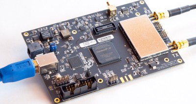
bladerf
The BladeRF, a modern SDR device that can receive and transmit signals between 300 MHz and 3 GHz

This flexibility means that SDR devices can handle a huge range of signals at relatively low cost. The $420 BladeRF, for instance, can receive and transmit signals from 300 MHz to 3.8 GHz at the same time, while the $300 HackRF One can work with signals from 1 MHz up to an incredible 6 GHz. The ability of the BladeRF to both receive and transmit means that you can use it to build your own GSM phone network, while the low cost of the HackRF One makes it a favorite of radio hackers who want to do things like make portable radio analyzers. Mass produced models are even cheaper: by hacking a $20 USB TV receiver that contains an SDR, you can get a radio that can, with a suitable antenna, do things like track airplanes or receive satellite weather images. And all of this is possible because of the idea of Software Defined Radio.

[Main image source: DVB dongle by Dsimic on Wikipeda CC-BY-SA]
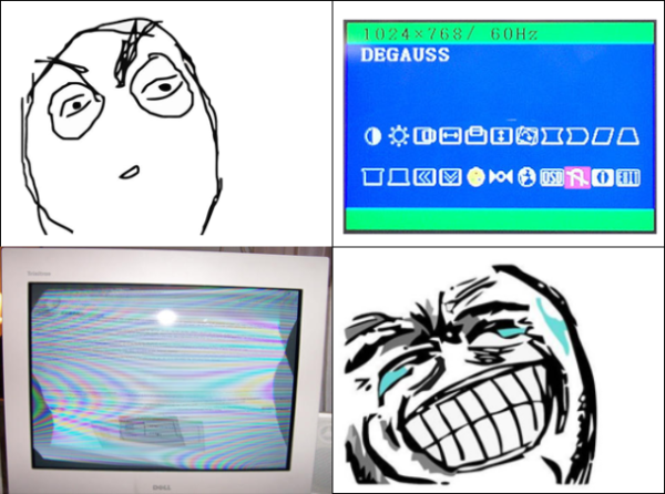
WTF Is Degaussing?

The modern office has become a sea of LCD monitors. It’s hard to believe that only a few years ago we were sitting behind Cathode Ray Tubes (CRTs). People have already forgotten the heat, the dust, and the lovely high frequency squeal from their flyback transformers.

Image by Søren Peo Pedersen via wikipedia

There was one feature of those old monitors which seems to be poorly understood. The lowly degauss button. On some monitors it was a physical button. On others, it was a magnet icon on the On Screen Display (OSD). Pressing it rewarded the user with around 5 seconds of a wavy display accompanied by a loud hum.

But what exactly did this button do? It seems that many never knew the purpose of that silly little button, beyond the light-and-sound show. The truth is that degaussing is rather important. Not only to CRTs, but in many other electronic and industrial applications.


Of Shadow Masks and Aperture Grilles

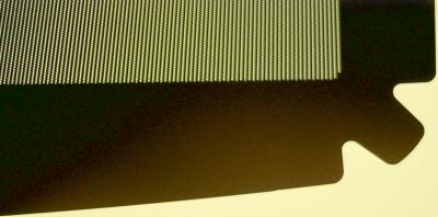
Close up of a shadow mask by Rauenstein via Wikipedia

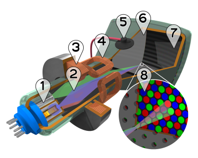
A CRT has quite a few components. There are three electron guns as well as steering and convergence coils at the rear (yoke) of the tube. The front of the tube has a phosphor-coated glass plate which forms the screen. Just behind that glass is a metal grid called the shadow mask. If you had enough money for a Sony screen, the shadow mask was replaced by the famous Trinitron aperture grille, a fine mesh of wires which performed a similar function. The shadow mask or aperture grille’s  job is to ensure that the right beams of electrons hit the red, green, or blue phosphor coatings on the front of the screen.

This all required a very precise alignment. Any stray magnetic fields imprinted on the mask would cause the electron beams to bend as they flew through the tube. Too strong a magnetic field, and your TV or monitor would start showing rainbows like something out of a 1960’s acid trip movie. Even the Earth’s own magnetic field could become imprinted on the shadow mask. Simply turning a TV from North to East could cause problems. The official term for it was “Color Purity”.

magnet-trickThese issues were well known from the early days of color TV sets. To combat this, manufacturers added a degaussing coil to their sets. A coil of wire wrapped around the front of the tube, just behind the bezel of the set. When the set was powered on, the coil would be fed with mains voltage. This is the well-known ‘fwoomp and buzz’ those old TV sets and monitors would make when you first turned them on. The 50 Hz or 60 Hz AC would create a strong moving magnetic field. This field would effectively erase the imprinted magnetic fields on the shadow mask or aperture grille.
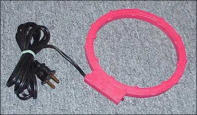


Running high current through the thin degaussing coil would quickly lead to a fire. Sets avoided this by using a Positive Temperature Coefficient (PTC) thermistor in-line with the coil. The current itself (or a small heating coil) would heat up the PTC, causing resistance to increase, and current through the coil to drop. After about 5 seconds, the coil was completely shut down, and the screen was (hopefully) degaussed.

As time went on monitors became embedded systems. The PTC devices were replaced by transistors controlled by the monitor’s main microcontroller. Monitor manufacturers knew that their sets were higher resolution than the average TV set, and thus even more sensitive to magnetic fields. Users are also more likely to move a monitor while using it. This lead the manufacturers to add a degauss button to the front of their sets. A push of the button would energize the coil for a few seconds under software control. Some monitors would also limit the number of times a user could push the button, ensuring the coil didn’t get too hot.

Holding a magnet near the front of a black and white (or a monochrome ‘green screen’) CRT created visible distortion, but no lasting damage. Mid-century hackers who tried the same trick with their first color TV quickly learned that the rainbow effect stayed long after the magnet was moved away. In extreme cases like these, the internal degaussing coil wouldn’t be strong enough to clear the shadow mask.

Commercial degaussing coil

When all else failed, a handheld degaussing coil or wand could be used. Literally waving the magic wand in front of the screen would usually clear things up. It was of course possible to permanently damage the shadow mask. Back in 2007, I was working for a radar company which had been slow to switch to LCD monitors. Being a radar shop, we had a few strong magnetron magnets lying around. One of these magnets was passed around among the engineers. Leaving the magnet under your monitor overnight would guarantee rainbows in the morning, and a shiny new LCD within a few days.

1024px-RMS_Queen_Mary_20Jun1945_NewYork
Queen Mary, showing her degaussing coil

CRTs aren’t the only devices which use degaussing coils. The term was originally coined in 1945 by Charles F. Goodeve of the Royal Canadian Naval Volunteer Reserve (RCNVR). German mines were capable of detecting the magnetic fields in a naval ship’s steel hull. Coils were used to mask this field. The Queen Mary is one of the more famous ships fitted with a degaussing coil to avoid the deadly mines.

Even mechanical wristwatches can benefit from a bit of degaussing. A watch which has been magnetized will typically run fast. Typically this is due to the steel balance spring becoming a weak magnet. The coils of the spring stick together as the balance wheel winds and unwinds each second. A degaussing coil (or in this case, more properly a demagnetizer) can quickly eliminate the problem.

A story on degaussing wouldn’t be complete without mentioning magnetic media. Handheld or tabletop degaussing coils can be used to bulk erase floppy disks, magnetic tape, even hard disks. One has to wonder if the degaussing coils in monitors were responsible for floppy disks becoming corrupted back in the old days.

So there you have it. The magic degaussing button demystified!

Why I Go Through So Many Arduinos

I make things for people that can’t be bought off a shelf, and in the past several years I have gone through a lot of Arduinos. More and more, they are simply the right tool for both the job and the client. This wasn’t always the case; what changed?

My clients today still include startups and other small businesses, but more and more they’re artists, hobbyists venturing into entrepreneurship, or people who make one-offs like the interactive displays you find in museums or science centers. The type of people I work for has changed, and because of this, the right tool for their job is almost always an Arduino.

Continue reading “Why I Go Through So Many Arduinos” →

Hackaday’s Fun With International Mains Plugs And Sockets

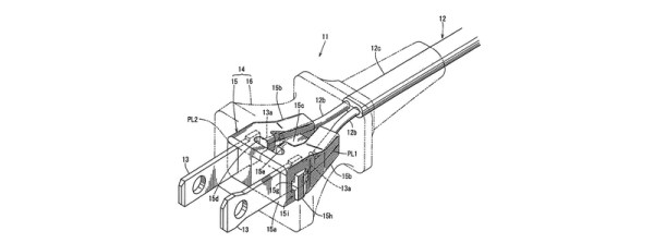
When we recently covered the topic of high voltage safety with respect to mains powered equipment, we attracted a huge number of your comments but left out a key piece of the puzzle. We take our mains plugs and sockets for granted as part of the everyday background of our lives, but have we ever considered them in detail? Their various features, and their astonishing and sometimes baffling diversity across the world.

When you announce that you are going to talk in detail about global mains connectors, it is difficult not to have an air of Sheldon Cooper’s Fun With Flags about you. But jokes and the lack of a co-starring Mayim Bialik aside, there is a tale to be told about their history and diversity, and there are also lessons to be taken on board about their safety. Continue reading “Hackaday’s Fun With International Mains Plugs And Sockets” →

It’s Time For Direct Metal 3D-Printing

It’s tough times for 3D-printing. Stratasys got burned on Makerbot, trustful backers got burned on the Peachy Printer meltdown, I burned my finger on a brand new hotend just yesterday, and that’s only the more recent events. In recent years more than a few startups embarked on the challenge of developing a piece of 3D printing technology that would make a difference. More colors, more materials, more reliable, bigger, faster, cheaper, easier to use. There was even a metal 3D printing startup, MatterFab, which pulled off a functional prototype of a low-cost metal-powder-laser-melting 3D printer, securing $13M in funding, and disappearing silently, poof.

This is just the children’s corner of the mall, and the grown-ups have really just begun pulling out their titanium credit cards. General Electric is on track to introduce 3D printed, FAA-approved fuel nozzles into its aircraft jet engines, Airbus is heading for 3D-printed, lightweight components and interior, and SpaceX has already sent rockets with 3D printed Main Oxidizer Valves (MOV) into orbit, aiming to make the SuperDraco the first fully 3D printed rocket engine. Direct metal 3D printing is transitioning from the experimental research phase to production, and it’s interesting to see how and why large industries, well, disrupt themselves.

Continue reading “It’s Time For Direct Metal 3D-Printing” →

To See Within: Making Medical X-rays

I was a bit of a lost soul after high school.  I dabbled with electrical engineering for a semester but decided that it wasn’t for me – what I wouldn’t give for a do-over on that one. In my search for a way to make money, I stumbled upon radiologic technology – learning how to take X-rays. I figured it was a good way to combine my interests in medicine, electronics, and photography, so after a two-year course of study I got my Associates Degree, passed my boards, and earned the right to put “R.T.(R) (ARRT)” after my name.

That was about as far as that career went. There are certain realities of being in the health care business, and chief among them is that you really have to like dealing with the patients. I found that I liked the technology much more than the people, so I quickly moved on to bigger and better things. But the love of the technology never went away, so I thought I’d take a look at exactly what it takes to produce medical X-rays, and see how it’s changed from my time in the Radiology Department.

Continue reading “To See Within: Making Medical X-rays” →

Don’t Ignore The Artist’s Supply Store

So it’s Saturday morning and you’ve found yourself with an urge to build something involving copper plates or carbon electrodes. Maybe you need a metallic powder for a chemistry experiment. Casting supplies? Pure lead? Copper mesh? Silver wire?  Odd tools? Exceedingly caustic etchants?  There’s a store that sells it all, and it’s not usually frequented by hackers: the art store.

If you know where to look, the store is full of useful things. Each method of expression in art has its own set of supplies; a bountiful collection of various processes and the useful things therein. I grew up in a city that did not have a real art supply store. It had one of those big box craft stores that assault you with glittery plasticized flowers and terrible manufactured scents. When I moved to a different city and walked over to the local art supply to purchase some new pens I ended up staying for a few hours just looking at all the cool things they had for sale.

Continue reading “Don’t Ignore The Artist’s Supply Store” →