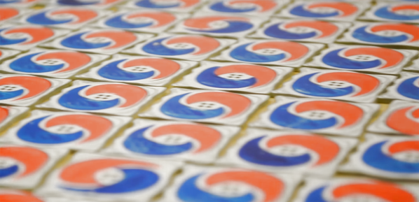
Linux Fu: Scripting For Binary Files

If you ever need to write a binary file from a traditional language like C, it isn’t all that hard to do. About the worst thing you might have to deal with is attempts to fake line endings across Windows and Linux, but there’s usually a way to turn that off if it is on by default. However, if you are using some type of scripting language, binary file support might be a bit more difficult. One answer is to use a tool like xxd or t2b (text-to-binary) to handle the details. You can find the code for t2b on GitHub including prebuilt binaries for many platforms. You should be able to install xxd from your system repository.

These tools take very different approaches. You might be familiar with tools like od or hexdump for producing readable representations of binary files. The xxd tool can actually do the same thing — although it is not as flexible. What xxd can even reverse itself so that it can rebuild a binary file from a hex dump it creates (something other tools can’t do). The t2b tool takes a much different approach. You issue commands to it that causes it to write an original hex file.

Both of these approaches have some merit. If you are editing a binary file in a scripting language, xxd makes perfect sense. You can convert the file to text, process it, and then roll it back to binary using one program. On the other hand, if you are creating a binary file from scratch, the t2b program has some advantages, too.

I decided to write a few test scripts using bash to show how it all works. These aren’t production scripts so they won’t be as hardened as they could be, but there is no reason they couldn’t be made as robust as you were willing to make them.

Continue reading “Linux Fu: Scripting For Binary Files”

Linux Fu: The Great Power Of Make

Over the years, Linux (well, the operating system that is commonly known as Linux which is the Linux kernel and the GNU tools) has become much more complicated than its Unix roots. That’s inevitable, of course. However, it means old-timers get to slowly grow into new features while new people have to learn all in one gulp. A good example of this is how software is typically built on a Linux system. Fundamentally, most projects use make — a program that tries to be smart about running compiles. This was especially important when your 100 MHz CPU connected to a very slow disk drive would take a day to build a significant piece of software. On the face of it, make is pretty simple. But today, looking at a typical makefile will give you a headache, and many projects use an abstraction over make that further obscures things.

In this article, I want to show you how simple a makefile can be. If you can build a simple makefile, you’ll find they have more uses than you might think. I’m going to focus on C, but only because that’s sort of the least common denominator. A make file can build just about anything from a shell prompt.

Continue reading “Linux Fu: The Great Power Of Make”

Buttery Smooth Fades With The Power Of HSV

In firmware-land we usually refer to colors using RGB. This is intuitively pleasing with a little background on color theory and an understanding of how multicolor LEDs work. Most of the colorful LEDs we are use not actually a single diode. They are red, green, and blue diodes shoved together in tight quarters. (Though interestingly very high end LEDs use even more colors than that, but that’s a topic for another article.) When all three light up at once the emitted light munges together into a single color which your brain perceives. Appropriately the schematic symbol for an RGB LED without an onboard controller typically depicts three discrete LEDs all together. So it’s clear why representing an RGB LED in code as three individual values {R, G, B} makes sense. But binding our representation of color in firmware to the physical system we accidentally limit ourselves.

The inside of an RGB LED

Last time we talked about color spaces, we learned about different ways to represent color spatially. The key insight was that these models called color spaces could be used to represent the same colors using different groups of values. And in fact that the grouped values themselves could be used to describe multidimensional spacial coordinates. But that post was missing the punchline. “So what if you can represent colors in a cylinder!” I hear you cry. “Why do I care?” Well, it turns out that using colorspace can make some common firmware tasks easier. Follow on to learn how!

Continue reading “Buttery Smooth Fades With The Power Of HSV”

Getting Good At FPGAs: Real World Pipelining

Parallelism is your friend when working with FPGAs. In fact, it’s often the biggest benefit of choosing an FPGA. The dragons hiding in programmable logic usually involve timing — chaining together numerous logic gates certainly affects clock timing. Earlier, I looked at how to split up logic to take better advantage of parallelism inside an FPGA. Now I’m going to walk through a practical example by modeling some functions. Using Verilog with some fake delays we can show how it all works. You should follow along with a Verilog simulator, I’m using EDAPlayground which runs in your browser. The code for this entire article is been pre-loaded into the simulator.

If you’re used to C syntax, chances are good you’ll be able to read simple Verilog. If you already use Verilog mostly for synthesis, you may not be familiar with using it to model delays. That’s important here because the delay through gates is what motivates us to break up a lot of gates into a pipeline to start with. You use delays in test benches, but in that context they mostly just cause the simulator to pause a bit before introducing more stimulus. So it makes sense to start with a bit of background on delays.

Continue reading “Getting Good At FPGAs: Real World Pipelining”

Pipelining Digital Logic In FPGAs

When you first learn about digital logic, it probably seems like it is easy. You learn about AND and OR gates and figure that’s not very hard. However, going from a few basic gates to something like a CPU or another complex system is a whole different story. It is like going from “Hello World!” to writing an operating system. There’s a lot to understand before you can make that leap. In this set of articles, I want to talk about a way to organize more complex FPGA designs like CPUs using a technique called pipelining.

These days a complex digital logic system is likely to be on an FPGA. And part of the reason we can get fooled into thinking digital is simple is because of the modern FPGA tools. They hide a lot of complexity from you, which is great until they can’t do what you want and then you are stuck. A good example of that is where you are trying to hit a certain clock frequency. If you aren’t careful, you’ll get a complaint from the tool that you can’t meet timing constraints.

Continue reading “Pipelining Digital Logic In FPGAs”

Optocouplers: Defending Your Microcontroller, MIDI, And A Hot Tip For Speed

Deep in the heart of your latest project lies a little silicon brain. Much like the brain inside your own bone-plated noggin, your microcontroller needs protection from the outside world from time to time. When it comes to isolating your microcontroller’s sensitive little pins from high voltages, ground loops, or general noise, nothing beats an optocoupler. And while simple on-off control of a device through an optocoupler can be as simple as hooking up an LED, they are not perfect digital devices.

But first a step back. What is an optocoupler anyway? The prototype is an LED and a light-sensitive transistor stuck together in a lightproof case. But there are many choices for the receiver side: photodiodes, BJT phototransistors, MOSFETs, photo-triacs, photo-Darlingtons, and more.

So while implementation details vary, the crux is that your microcontroller turns on an LED, and it’s the light from that LED that activates the other side of the circuit. The only connection between the LED side and the transistor side is non-electrical — light across a small gap — and that provides the rock-solid, one-way isolation.

Continue reading “Optocouplers: Defending Your Microcontroller, MIDI, And A Hot Tip For Speed”

How To Build Anything Out Of Aluminum Extrusion And 3D Printed Brackets

The real power of 3D printing is in infinite customization of parts. This becomes especially powerful when you combine 3D printing with existing materials. I have been developing a few simple tricks to make generic fasteners and printed connectors a perfect match for aluminum extrusion, via a novel twist or two on top of techniques you may already know.

Work long enough with 3D printers, and our ideas inevitably grow beyond our print volume. Depending on the nature of the project, it may be possible to divide into pieces then glue them together. But usually a larger project also places higher structural demands ill-suited to plastic.

Those of us lucky enough to have nice workshops can turn to woodworking, welding, or metal machining for larger projects. Whether you have that option or not, aluminum extrusion beams provide the structure we need to go bigger and to do it quickly. And as an added bonus, 3D printing can make using aluminum extrusion easier and cheaper.

Continue reading “How To Build Anything Out Of Aluminum Extrusion And 3D Printed Brackets”