The $2 32-Bit Arduino (with Debugging)

I have a bit of a love/hate relationship with the Arduino. But if I had two serious gripes about the original offering it was the 8-bit CPU and the lack of proper debugging support. Now there’s plenty of 32-bit support in the Arduino IDE, so that takes care of the first big issue. Taking care of having a real debugger, though, is a bit trickier. I recently set out to use one of the cheap “blue pill” STM32 ARM boards. These are available for just a few bucks from the usual Chinese sources. I picked mine up for about $6 because I wanted it in a week instead of a month. That’s still pretty inexpensive. The chip has a lot of great debugging features. Can we unlock them? You can, if you have the right approach.

The Part

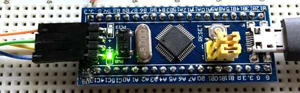
For a few bucks, you can’t complain about the hardware. The STM32F103C8T6 onboard is a Cortex-M3 processor that runs at 72 MHz. There’s 64K of flash and 20K of RAM. There’s a minimicro-USB that can act as a programming port (but not at first). There’s also many 5 V-tolerant pins, even though this a 3.3 V part.

You can find a lot more information on this wiki. The board is a clone–more or less–of a Maple Mini. In fact, that’s one way you can use these. You can use the serial or ST-Link port to program the Maple bootloader (all open source) and use it like a Maple. That is, you can program it via the USB cable.

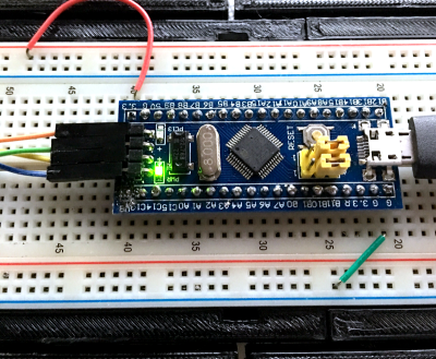
From my point of view, though, I don’t want to try to debugging over the serial port and if I have the ST-Link port already set up, I don’t care about a bootloader. You can get hardware that acts as a USB to ST-Link device inexpensively, but I happen to have an STM32VLDISCOVER board hanging around. Most of the STM32 demo boards have an ST-Link programmer onboard that is made to use without the original target hardware. On some of the older boards, you had to cut traces, but most of the new ones just have two jumpers you remove when you want to use the programmer to drive another device.

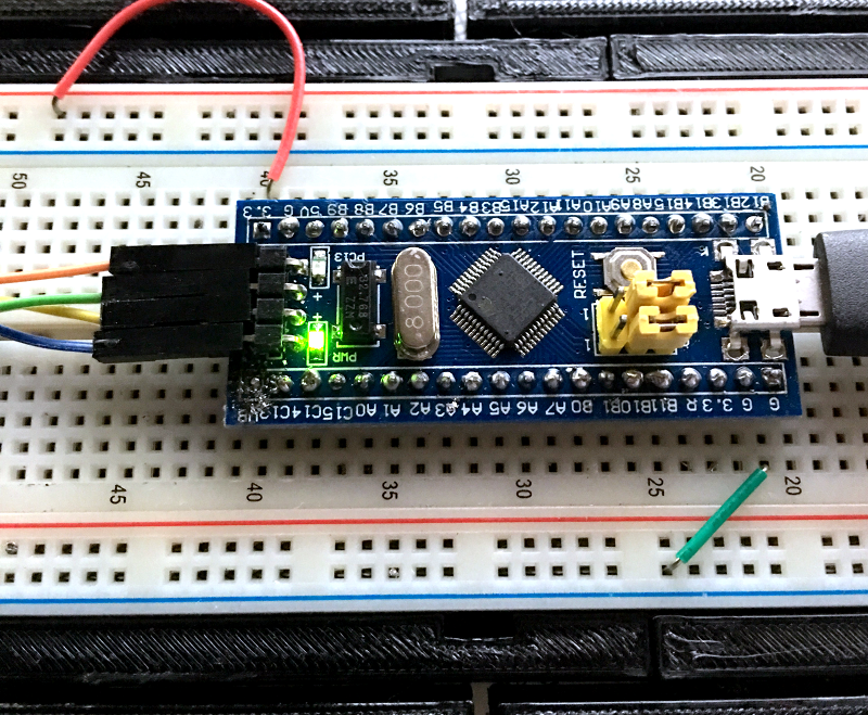
The “blue pill” designation is just a common nickname referring to the Matrix, not the pharmaceuticals you see on TV ads. The board has four pins at one edge to accommodate the ST-Link interface. The pin ordering didn’t match up with the four pins on the STM32VLDISCOVER, so you can’t just use a straight four-pin cable. You also need to bring power over to the board since it will have to power the programmer, too. I took the power from the STM32VLDISCOVER board (which is getting its power from USB) and jumpered it to my breadboard since that was handy.

Continue reading “The $2 32-Bit Arduino (with Debugging)”

Linux-Fu: Keeping Things Running

If you’ve used Linux from the early days (or, like me, started with Unix), you didn’t have to learn as much right away and as things have become more complex, you can kind of pick things up as you go. If you are only starting with Linux because you are using a Raspberry Pi, became unhappy with XP being orphaned, or you are running a cloud server for your latest Skynet-like IoT project, it can be daunting to pick it all up in one place.

Recently my son asked me how do you make something run on a Linux box even after you log off. I thought that was a pretty good question and not necessarily a simple answer, depending on what you want to accomplish.

There’s really four different cases I could think of:

  1. You want to launch something you know will take a long time.
  2. You run something, realize it is going to take a long time, and want to log off without stopping it.
  3. You want to write a script or other kind of program that detaches itself and keeps running (known as a daemon).
  4. You want some program to run all the time, even if you didn’t log in after a reboot.

Continue reading “Linux-Fu: Keeping Things Running”

Ask Hackaday: What’s Your Etchant?

Although the typical cliché for a mad scientist usually involves Bunsen burners, beakers, and retorts, most of us (with some exceptions, of course) aren’t really chemists. However, there are some electronic endeavors that require a bit of knowledge about chemistry or related fields like metallurgy. No place is this more apparent than producing your own PCBs. Unless you use a mill, you are probably using a chemical bath of some sort to strip copper from your boards.

The standard go-to solution is ferric chloride. It isn’t too tricky to use, but it does work better hot and with aeration, although neither are absolutely necessary. However, it does tend to stain just about everything it touches. In liquid form, it is more expensive to ship, although you can get it in dry form. Another common etchant is ammonium or sodium persulphate.

pcbyThere’s also a variety of homemade etchants using things like muriatic acid and vinegar. Most of these use peroxide as an oxidizer. There’s lots of information about things like this on the Internet. However, like everything on the Internet, you can find good information and bad information.

When [w_k_fay] ran out of PCB etchant, he decided to make his own to replace it and wrote a great guide on how this is done. He found a lot of vague and conflicting information on the Internet. He read that the vinegar solution was too slow and the cupric acid needs a heated tank, a way to oxygenate the solution, and strict pH controls. However, he did have successful experiments with the hydrochloric acid and peroxide. He also used the same materials (along with some others) to make ferric chloride successfully.

Continue reading “Ask Hackaday: What’s Your Etchant?”

Good In A Pinch: The Physics Of Crimped Connections

I had a friend who was an electronics assembly tech for a big defense contractor. He was a production floor guy who had a chip on his shoulder for the engineers with their fancy book-learnin’ who couldn’t figure out the simplest problems. He claimed that one assembly wasn’t passing QC and a bunch of the guys in ties couldn’t figure it out. He sidled up to assess the situation and delivered his two-word diagnosis: “Bad crimp.” The dodgy connector was re-worked and the assembly passed, much to the chagrin of the guys in the short-sleeved shirts.

Aside from the object lesson in experience sometimes trumping education, I always wondered about that “bad crimp” proclamation. What could go wrong with a crimp to so subtly futz with a circuit that engineers were baffled? How is it that we can rely on such a simple technology to wire up so much of the modern world? What exactly is going on inside a crimped connection anyway?

Continue reading “Good In A Pinch: The Physics Of Crimped Connections”

Taking The Leap Off Board: An Introduction To I2C Over Long Wires

If you’re reading these pages, odds are good that you’ve worked with I²C devices before. You might even be the proud owner of a couple dozen sensors pre-loaded on breakout boards, ready for breadboarding with their pins exposed. With vendors like Sparkfun and Adafruit popping I²C devices onto cute breakout boards, it’s tempting to finish off a project with the same hookup wires we started it with.

Image result for i2c sensor array
prototyping starts here, but we’re in danger when projects finish with this sort of wiring

It’s also easy to start thinking we could even make those wires longer — long enough to wire down my forearm, my robot chassis, or some other container for remote sensing. (Guilty!) In fact, with all the build logs publishing marvelous sensor “Christmas-trees” sprawling out of a breadboard, it’s easy to forget that I²C signals were never meant to run down any length of cable to begin with!

As I learned quickly at my first job, for industry-grade (and pretty much any other rugged) projects out there, running unprotected SPI or I²C signals down any form of lengthy cable introduces the chance for all sorts of glitches along the way.

I thought I’d take this week to break down that misconception of running I²C over cables, and then give a couple examples on “how to do it right.”

Heads-up: if you’re just diving into I²C, let our very own [Elliot] take you on a crash course. Continue reading “Taking The Leap Off Board: An Introduction To I2C Over Long Wires”

Creating A PCB In Everything: Upverter

For the last five months, I’ve been writing a series of posts describing how to build a PCB in every piece of software out there. Every post in this series takes a reference schematic and board, and recreates all the elements in a completely new PCB tool.

There are three reasons why this sort of review is valuable. First, each post in this series is effectively a review of a particular tool. Already we’ve done Fritzing (thumbs down), KiCad (thumbs up), Eagle (thumbs up), and Protel Autotrax (interesting from a historical perspective). Secondly, each post in this series is a quick getting started guide for each PCB tool. Since the reference schematic and board are sufficiently complex for 90% of common PCB design tasks, each of these posts is a quick how-to guide for a specific tool. Thirdly, this series of posts serves as a basis of comparison between different tools. For example, you can do anything you want in KiCad and most of what you want in Eagle. Fritzing is terrible, and Autotrax is the digital version of the rub-on traces you bought at Radio Shack in 1987.

With that introduction out of the way, let’s get cranking on Upverter.

A little bit about Upverter

Upverter was founded in 2010 as an entirely web-based EDA tool aimed at students, hobbyists, and Open Hardware circuit designers. This was one of the first completely web-based circuit design tools and Upverter’s relative success has been a bellwether for other completely web-based EDA tools such as circuits.io and EasyEDA.

I would like to take a second to mention Upverter is a Y Combinator company (W11), which virtually guarantees this post will make it to the top of Hacker News. Go fight for imaginary Internet points amongst yourselves.

Upverter is a business after all, so how are they making money? Most EDA suites offer a free, limited version for personal, hobbyist, and ‘maker’ projects, and Upverter is no exception. The professional tier offers a few more features including CAM export, 3D preview, an API, simulation (coming soon), BOM management, and unlimited private projects for $125 per seat per month, or $1200 per seat per year.

To give you a basis of comparison for that subscription fee, Eagle CAD’s new license scheme gives you everything – 999 schematic sheets, 16 layers, and unlimited board area – for $65 per month, or $500 per year. Altium’s CircuitStudio comes in at $1000 for a one-year license. There are more expensive EDA suites such as Altium Designer and OrCAD, but you have to call a sales guy just to get a price.

Upverter is positioning itself as a professional tool at a professional price. There are better tools out there, of course, but there are thousands of businesses out there designing products with tools that cost $500 to $1000 per seat per year. In any event, this is all academic; the Hackaday crowd gravitates towards the free end of the market, whether that means beer or speech.

A big draw for Upverter is their Parts Concierge service. You’ll never have to create a part from scratch again, so the sales copy says. Apparently, Upverter is using a combination of very slick scripts to pull part layouts off a datasheet and human intervention / sanity check to create these parts. Does it work? We’re going to find out in the review below.

Continue reading “Creating A PCB In Everything: Upverter”

Increase The Range Of An ESP8266 With Duct Tape

For the longest time now, I’ve wanted to build a real, proper radio telescope. To me, this means a large parabolic reflector, a feed horn made of brass sheet, coat hanger wire, and at least for the initial experiments, an RTL-SDR dongle. I’ve done the calculations, looked at old C-band antennas on Craigslist, and even designed a mount or two that would make pointing the dish possible. I’ve done enough planning to know the results wouldn’t be great. After months of work, the best I could ever hope for is a very low-resolution image of the galactic plane. If I get lucky, there might be a bright spot corresponding to Sagittarius A.

There are better ways to build a radio telescope in your back yard, but the thought of having a gigantic parabolic dish out back, peering into the heavens, has stuck with me. I’ve even designed a dish that can be taken apart easily and transported because building your own dish is far cooler than buying a West Virginia state flower from a guy on Craigslist.

Recently, I was asked to come up with a futuristic, space-ey prop for an upcoming video. My custom-built, easily transportable parabolic antenna immediately sprang to mind. The idea of a three-meter diameter parabolic dish was rejected for something a little more practical and a little less expensive, but I did go so far as to do a few more calculations, open up a CAD program, and start work on the actual design. As a test, I decided to 3D print a small model of this dish. In creating this model, I inadvertently created the perfect WiFi antenna for an ESP8266 module using nothing but 3D printed parts, a bit of epoxy, and duct tape.

Continue reading “Increase The Range Of An ESP8266 With Duct Tape”