Last time, I talked about racing the beam, a type of graphics used when memory was scarce. Now it’s time to step into the future with more memory and talk about what modern 2D games still do to this day: rasterization.
Just in time Memory
Continuing the trend set by racing the beam, rasterized graphics are also on a grid, just a much tinier one. Though not unique to rasterized, the “frame buffer” is the logical conclusion of bitmap mode fidelity: enough memory is allocated so that every pixel can have its own color. What’s different about a frame buffer is that everything is drawn before it is shown and, crucially, this doesn’t have to happen in the same order as the pixels are displayed. Rasterization draws entire shapes — triangles, lines and rectangles — into the frame buffer and the screen is typically updated all at once. Continue reading “Game Graphics: Rasterization”→
Will Rogers once said that veterinarians are the best doctors because their patients can’t tell them where it hurts. I’ve often thought that electronic people have a similar problem. In many cases, what’s wrong with our circuits isn’t visible. Sure, you can visually identify a backward diode, a bad solder joint, or a blown fuse. But you can’t look at a battery and see that it is dead or that a clock signal isn’t reaching some voltage. There are lots of ways to look at what’s really going on, but there is no substitute for a scope. It used to be hard for the average person to own a scope, but these days, it doesn’t require much. If you aren’t shopping for the best tech or you are willing to use it with a PC, oscilloscopes are quite affordable. If you spend even a little, you can now get scopes that are surprisingly capable with features undreamed of in years past. For example, many modern scopes have a dizzying array of triggering options. Do you need them? What do they do? Let’s find out.
I’ll be using a relatively new Rigol DHO924S, but none of the triggering modes are unique to that instrument. Sometimes, they have different names, and, of course, their setup might look different than my pictures, but you should be able to figure it out.
What is Triggering?
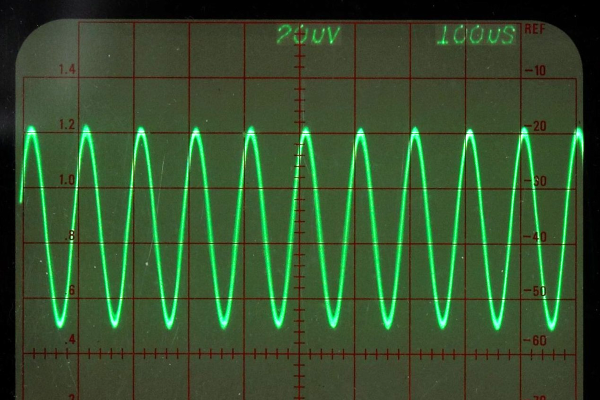
In simple terms, an oscilloscope plots time across the X-axis and voltage vertically on the Y-axis. So you can look at two peaks, for example, and measure the distance between them to understand how far apart they are in time. If the signal you are measuring happens repeatedly — like a square or sine wave, for example — it hardly matters which set of peaks you look at. After all, they are all the same for practical purposes.
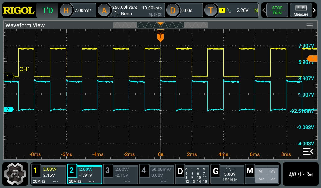
Pretty square waves all in a row. Channel 2 is 180 degrees out of phase (inverted). But is that all there is?
The problem occurs when you want to see something relative to a particular event. Basic scopes often have level triggering. They “start” when the input voltage goes above or below a certain value. Suppose you are looking at a square wave that goes from 0 V to 5 V. You could trigger at about 2.5 V, and the scope will never start in the middle of a cycle.
Digital scopes tend to capture data before and after the trigger, so the center of the screen will be right on an edge, and you’ll be able to see the square waves on either side. The picture shows two square waves on the screen with the trigger point marked with a T in the top center of the display. You can see the level in the top bar and also marked with a T on the right side of the screen.
What happens if there are no pulses on the trigger source channel? That depends. If you are in auto mode, the scope will eventually get impatient and trigger at random. This lets you see what’s going on, but there’s no reference. If you are in normal mode, though, the scope will either show nothing or show the last thing it displayed. Either way, the green text near the top left corner will read WAIT until the trigger event occurs. Then it will say T’D.
Last time, I assembled a Python object representing a Rigol oscilloscope. Manipulating the object communicates with the scope over the network. But my original goal was to build a little GUI window to sit next to the scope’s web interface. Had I stuck with C++ or even C, I would probably have just defaulted to Qt or maybe FLTK. I’ve used WxWidgets, too, and other than how many “extra” things you want, these are all easy enough to use. However, I had written the code in Python, so I had to make a choice.
Granted, many of these toolkits have Python bindings — PyQt, PySide, and wxPython come to mind. However, the defacto GUI framework for Python is Tkinter, a wrapper around Tk that is relatively simple to use. So, I elected to go with that. I did consider PySimpleGUI, which is, as the name implies, simple. It is attractive because it wraps tkinter, Qt, WxPython, or Remi (another toolkit), so you don’t have to pick one immediately. However, I decided to stay conservative and stuck with Tkinter. PySimpleGUI does have a very sophisticated GUI designer, though.
About Tkinter
The Tkinter toolkit lets you create widgets (like buttons, for example) and give them a parent, such as a window or a frame. There is a top-level window that you’ll probably start with. Once you create a widget, you make it appear in the parent widget using one of three layout methods:
Absolute or relative coordinates in the container
“Pack” to the top, bottom, left, or right of the container
Row and column coordinates, treating the container like a grid
The main window is available from the Tk() method:
That’s about the simplest example. Make a button and close the program when you push it. The mainloop call handles the event loop common in GUI programs.
It used to be only high-end test equipment that had some sort of remote control port. These days, though, they are quite common. Historically, test gear used IEEE-488 (also known as GPIB or, from the originator, HPIB). But today, your device will likely talk over a USB port, a serial port, or a LAN connection. You’d think that every instrument had unique quirks, and controlling it would be nothing like controlling another piece of gear, especially one from another company. That would be half right. Each vendor and even model indeed has its unique command language. There has been a significant effort to standardize some aspects of test instrument control, and you can quickly write code to control things on any platform using many different programming languages. In a few posts, I will show you just how easy it can be.
The key is to use VISA. This protocol is defined by the IVI Foundation that lets you talk to instruments regardless of how they communicate. You do have to build an address that tells the VISA library how to find your device. For example: “TCPIP::192.168.1.92::INSTR.” But once you have that, it is easy to talk to any instrument anywhere.
I say that thinking it is a problem is half right because talking to the box is one task of the two you need to complete. The other is what to say to the box and what it will say back to you. There are a few standards in this area, but this is where you get into problems. Continue reading “How To Talk To Your Scope”→
If you grow up around a working blacksmith’s forge, there are a few subjects related to metalwork on which you’ll occasionally have a heated discussion. Probably the best known is the topic of wrought iron, a subject I’ve covered here in the past, and which comes from the name of a particular material being confused with a catch-all term of all blacksmith-made items. I’ve come to realise over recent years that there may be another term in general use which is a little jarring to metalwork pedants, so-called Damascus steel. Why the Syrian capital should pop up in this way is a fascinating story of medieval metalworking, which can easily consume many days of research.
Damascus? Where’s That?
The banded pattern of the laminate formed from pattern welded layers of differing steels in a modern Damascus steel knife. “DamaszenerKlinge” by Soerfm
The Damascus steel you’ll see in YouTube videos, TV shows, and elsewhere is a steel with complex bands and striations on its surface. It’s often used in knife blades, and it will usually have been chemically treated to enhance the appearance of the patterns. It’s a laminate material made by pattern welding layers of different steels together, and it will usually have been worked and folded many times to produce a huge number of very thin layers of those steels. Sometimes it’s not made from sheets or ingots of steel but from manufactured steel products such as chains, in an attempt to produce a result with more unusual patterns. Continue reading “When Is Damascus Steel Not From Damascus?”→
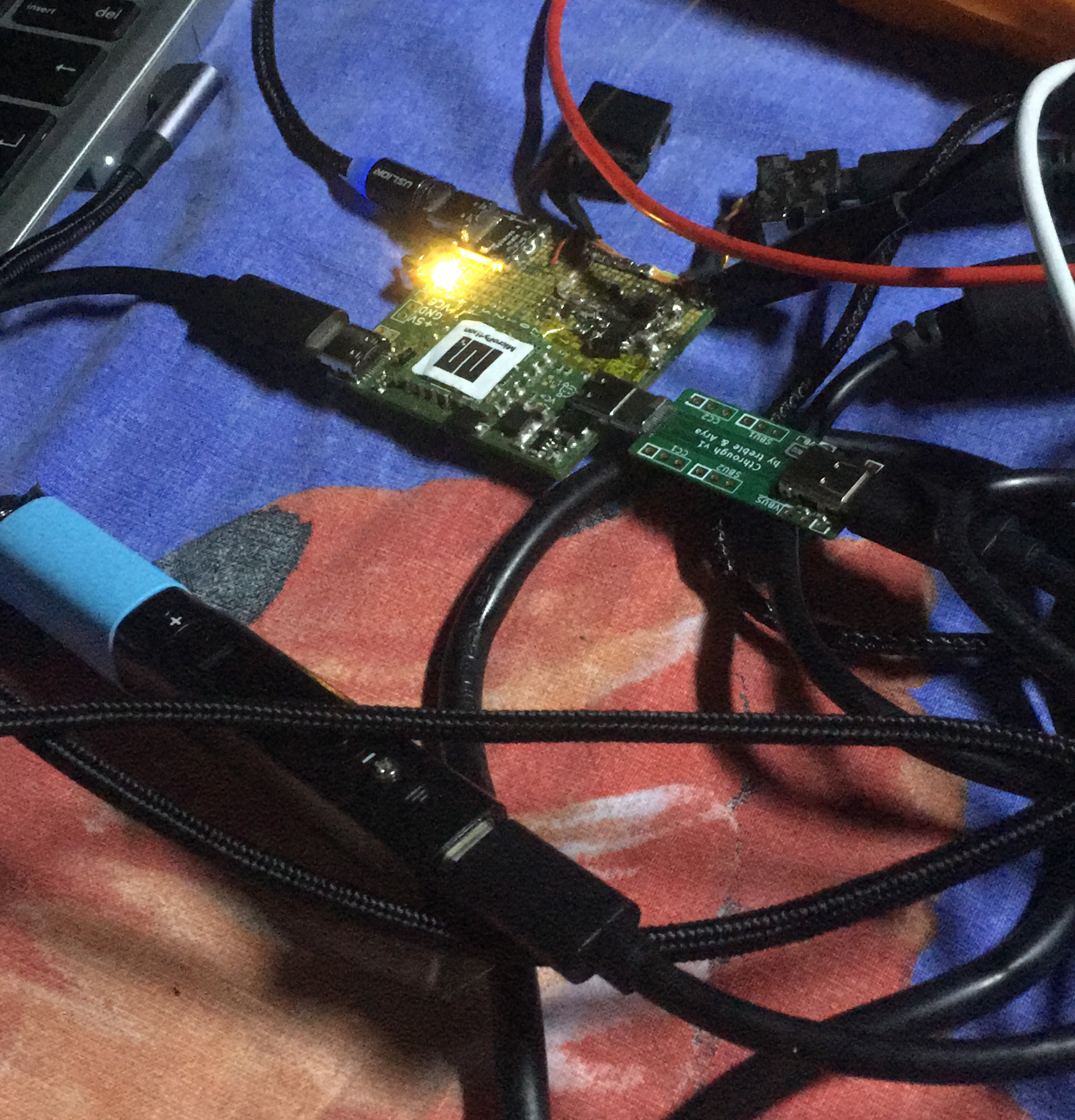
What if you wanted to build your own USB-C PSU? Good news – it’s easy enough! If you ever wanted to retrofit a decent DC PSU of yours to the USB-C standard, say, you got a Lenovo/HP/Dell 19V-20V charger brick and you’ve ever wished it were USB-C, today is the day when we do exactly that. To be fair, we will cheat a bit – but only a tiny bit, we won’t be deviating too much from the specification! And, to begin with, I’ll show you some exceptionally easy ways that you can turn your DC PSU into a USB-C compatible one, with a simple module or a few.
Turning a 20 V PSU into a USB-C PSU feels natural if you want to charge a laptop – those tend to request 20 V from a USB-C PSU anyway, so what’s the big deal? However, you can’t just put 20 V onto a USB-C connector – you have to add a fair bit of extra logic to make your newly christened USB-C PSU safe to use with 5 V devices, and this logic also requires you go through a few extra steps before 20 V appears on VBUS. Any USB-C PSU has to output 5 V first and foremost whenever a device is connected, up until a higher voltage is negotiated digitally, and the PSU may only switch to a higher voltage output when it’s requested to do so.
Now, for that, a PSU offers a list of profiles, and we looked into those profiles in the Replying PD article – each profile is four bytes that contain information about the profile voltage, maximum current that the device may draw at that voltage, and a few other details. For a PSU to be USB-C compliant, the USB-C specification says that, in addition to 5 V, you may also offer 9 V, 15 V, and 20 V.
Also, the specification says that if a PSU supports certain in-spec voltage like 15 V, it’s also required by the spec to offer all of the spec-defined voltages below the maximum one – for 15 V, that also requires supporting 9 V. Both of these are UX requirements, as opposed to technical requirements – it’s easier for device and PSU manufacturers to work with a small set of pre-defined voltages that majority of the chargers will support, but in reality, you can actually offer any voltage you want in the PSU advertisement; at worst, a device is going to refuse and contend with slowly charging from the 5 V output that you’re required to produce.
After years of seeing people showing off and trading their badge Simple Add-Ons (SAOs) at Supercon, this year I finally decided to make one myself. Now for a first attempt, it would have been enough to come up with some cool PCB art and stick a few LEDs on it. But naturally I started with a concept that was far more ambitious than necessary, and before long, had convinced myself that the only way to do the thing justice was to have an onboard microcontroller.
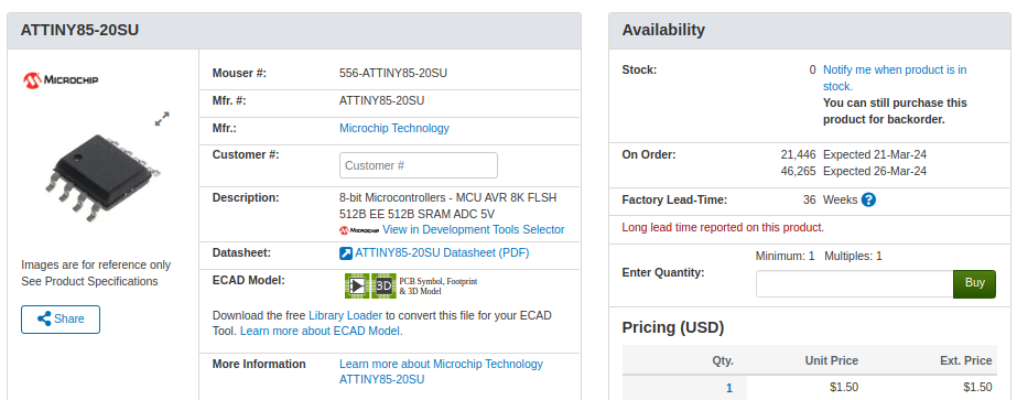
My first thought was to go with the venerable ATtiny85, and since I already had a considerable stock of the classic eight-pin DIP MCUs on hand, that’s what I started prototyping with. After I had something working on the breadboard, the plan was to switch over to the SOIC-8 version of the chip which would be far more appropriate for something as small as an SAO.
Unfortunately, that’s where things got tricky. I quickly found that none of the major players actually had the SMD version of the chip in stock. Both DigiKey and Mouser said they didn’t expect to get more in until early 2024, and while Arrow briefly showed around 3,000 on hand, they were all gone by the time I checked back. But that was only half the problem — even if they had them, $1.50 a piece seems a hell of a lot of money for an 8-bit MCU with 8K of flash in 2023.
The whole thing was made all the more frustrating by the pile of DIP8 ATtiny85s sitting on the bench, mocking me. Under normal circumstances, using them in an SAO wouldn’t really be a problem, but eight hand-soldered leads popping through the front artwork would screw up the look I had in mind.
While brooding over the situation my eyes happened to fall on one of the chips I had been fiddling with, it’s legs badly bent from repeated trips through the programmer. Suddenly it occurred to me that maybe there was a way to use the parts I already had…