Anyone in the know about IoT security is likely to steer clear of a physical security product that’s got some sort of wireless control. The list of exploits for such devices is a long, sad statement on security as an afterthought, if at all. So it’s understandable if you think a Bluetooth-enabled lock is best attacked via its wireless stack.
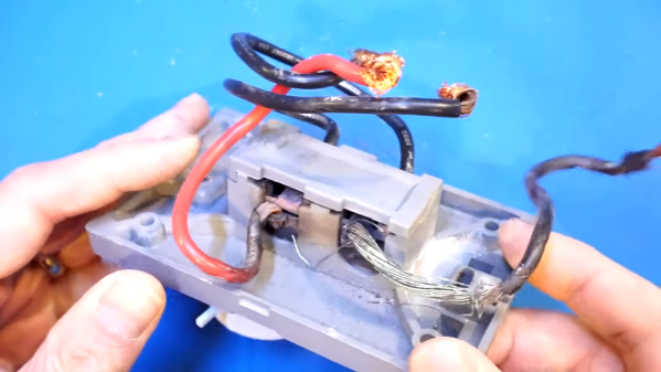
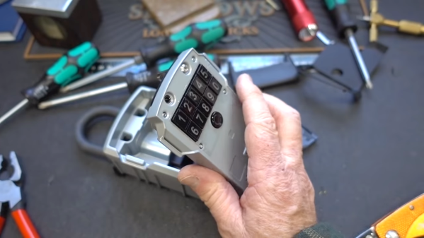
As it turns out, the Master 5440D Bluetooth Key Safe can be defeated in a few minutes with just a screwdriver. The key safe is the type a realtor or AirBnB host would use to allow access to a property’s keys. [Bosnianbill] embarked on an inspection of the $120 unit, looking for weaknesses. When physical attacks with a hammer and spoofing the solenoids with a magnet didn’t pay off, he decided to strip off the resilient skin that Master so thoughtfully provided to prevent the box from marring the finish of a door or gate. The denuded device thus revealed its awful secret: two Phillips screws, each securing a locking shackle to the cover. Once those are loose, a little prying with a screwdriver is all that’s need to get the keys to the kingdom.
In a follow-up video posted later, [Bill] took a closer look at another key safe and found that Master had made an anemic effort to fix this vulnerability with a squirt of epoxy in each screw head. It’s weak, at best, since a tap with a hammer compresses the gunk enough to get a grip on the screw.
We really thought [Bosnianbill]’s attack would be electronic, like that time [Dave Jones] cracked a safe with an oscilloscope. Who’d have thought a screwdriver would be the best way past the wireless stack?
Continue reading “Fail Of The Week: Padlock Purports To Provide Protection, Proves Pathetic”