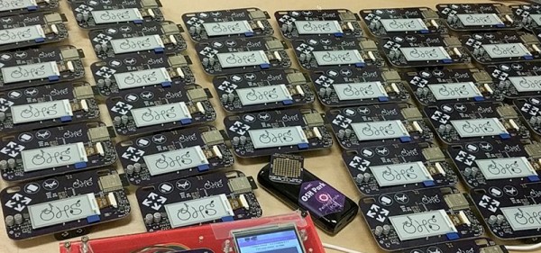
The past few years have been all about electronic conference badges and this year is no different. Right now, we’re setting up at the Open Hardware Summit at MIT, and this year’s badge is nothing short of extraordinary. It’s a WiFi and Bluetooth-enabled e-paper badge, individually programmed for every attendee. The 2018 Open Hardware Summit badge is a work of art, and it was all created over on hackaday.io.
This board is based on the ESP trINKet designed by [Mike Rankin] with additional hardware design from [Alex Camilo]. The badge is based around the ESP32-wroom-32 module with a 2.13 inch e-paper display with a resolution of 250 x 122 pixels. To this, the badge adds an I2C accelerometer and support for add-ons. There’s also pads for an SD card holder — a soldering challenge, if you will — and few additional pads for bits and bobs.
But a badge is nothing without software, and that’s where this really gets good. The ESP32 module is a powerhouse, capable of emulating NES games or serving as a file server. Here, the stock configuration of the badge is rather simplistic: you can start a WiFi AP, log onto a web page, and change the name displayed on the badge. You can also start an FTP server, which is where things get really fun. Drop an application on that FTP server, and you can run Micro Python.
The badge is great, but the programming jig is awesome
The boards were made through OSH Park, and Screaming Circuits took care of the assembly. Anyone who has ever built a badge will tell you it isn’t the assembly that gets you — it’s the programming and provisioning. This is especially true since the Open Hardware Summit badge is distributed with the attendee’s names already preloaded. That’s a few hundred badges, all with unique firmware. This is a nightmare by any definition.
However, there’s always a good solution to a problem, and [Drew] from OSH Park showed me the best programming jig I’ve ever seen during the Summit pre-game at Artisan’s Asylum.
What you’re looking at is a 3D printed box loaded up with a touch-screen display, a Raspberry Pi Zero W, and a few pogo pins. This Raspberry Pi does all the heavy lifting by connecting to the Internet, pulling down the current version of the firmware, and loading that firmware onto the badge. There are a few more options thanks to the touch-screen interface, including provisioning all the badges with the names of the attendees — this can be done by reading a list of attendees and uploading the next one to the badge in the jig. All of this is wrapped up with a nice laser-cut cover that securely holds each badge exactly where it needs to be for the pogo pins to make contact.
This is, without question, the best programming jig I’ve seen. Any badge makers out there should take note: this is how you program a few hundred badges. The badge, itself, is great and just as this post is published there will be hundreds of eager hackers futzing about with this remarkable piece of hardware. If you want to check out the current progress of the badge hacking, check out the updates on Twitter


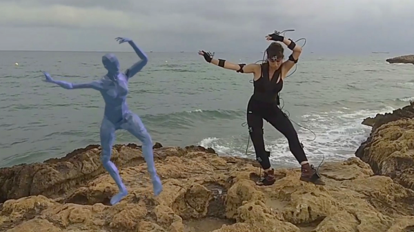
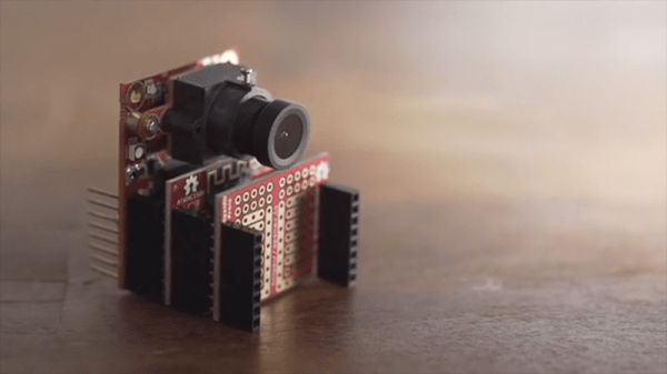
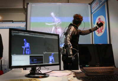 Fifteen sensor boards, called K-Ceptors, are attached to various points on the body, each containing an LSM9DS1 IMU (Inertial Measurement Unit). The K-Ceptors are wired together while still allowing plenty of freedom to move around. Communication is via I2C to a Raspberry Pi. The Pi then sends the collected data over WiFi to a desktop machine. As you move around, a 3D model of a human figure follows in realtime, displayed on the desktop’s screen using Blender, a popular, free 3D modeling software. Of course, you can do something else with the data if you want, perhaps make a robot move? Check out the overview and the performance by a clearly experienced dancer putting the system through its paces in the video below.