If you’ve built a 3D printer, CNC, laser cutter, or basically any piece of electrical equipment that moves around, then you’ve run into the problem of securing the bundle of wires that such machines always require. The easy way out is to zip tie them all up into a tight harness or put them in commercially available wraps or sleeves, but these don’t really impart any mechanical strength on the wires. With repetitive motion it’s not unheard of to break a conductor or two, causing intermittent failures and generally leading to a painful diagnostic session trying to isolate the broken wire.
 An alternative are what are generally referred to as “cable chains”. These are rigid enclosures for your wiring that not only keep things tidy, but give the wires the mechanical support necessary to prevent fatigue. Unfortunately, they are often many times more expensive than a simple wire wrap or pack of zip ties. But [Brad Parcels] has written into our tip line to share with us a sort of hybrid approach to wire management that has many of the same advantages as a traditional cable chain, but at a greatly reduced cost.
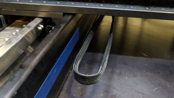
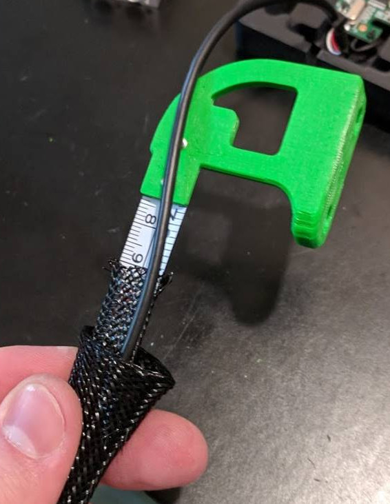
The key to the design is using the metallic tape from a cheap tape measure to give the bundle of wires some mechanical strength. As anyone who’s ever played around with a tape measure knows, if you bend the tape over into a U shape it will hold the bend even if you extend and retract it. Thanks to this principle, [Brad] realized that all he need to do was add some wire sleeves and he would have a cheap and effective way to keep his wiring neat and sag-free.
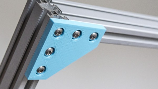
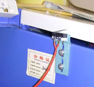
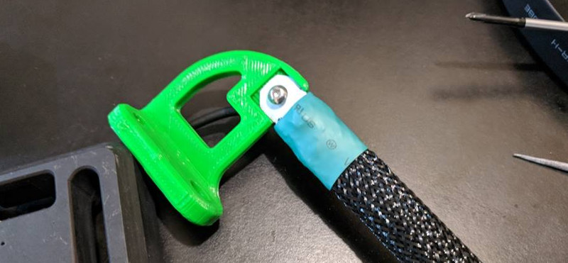
[Brad] punches holes in the tape to secure it to his 3D printed mounting arms, but really any method of securing the tape to the frame of your machine will work just as well. He then slides a cable sleeve over the tape itself to protect from any possibility of the edge of the tape nicking a wire, and then finally a larger wire sleeve over the entire assembly.
After running the wires between the two sleeves, heatshrink can be used on the ends to neatly close everything up. Just make sure you remember all your wires before you seal it, [Brad] learned that one the hard way. But overall, he reports this DIY cable chain arrangement has been working wonderfully in his machine, providing smooth and silent movement for only a few bucks.
Cable management for projects that move is one of those things that doesn’t always get the attention it deserves. Not only can it keep your project looking professional, but it just might save you some time down the road by preventing failures.