Space Technology And Audio Tape To Store Art

[Blaine Murphy] has set out to store an archive of visual art on cassette tape. To do so he encodes images via Slow-Scan Television (SSTV), an analogue technology from the late 50s which encodes images in for radio transmission. If you are thinking ‘space race’ you are spot on, the first images of the far side of the moon reached us via SSTV and were transmitted by the soviet Luna 3 spacecraft.

Yes, this happened

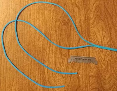
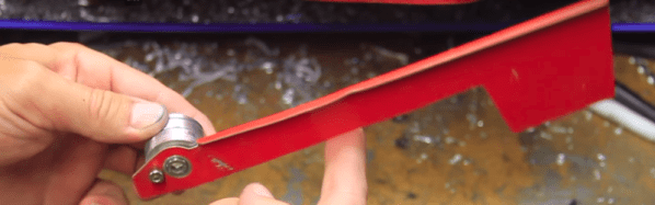
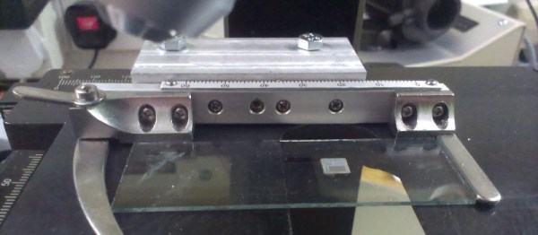
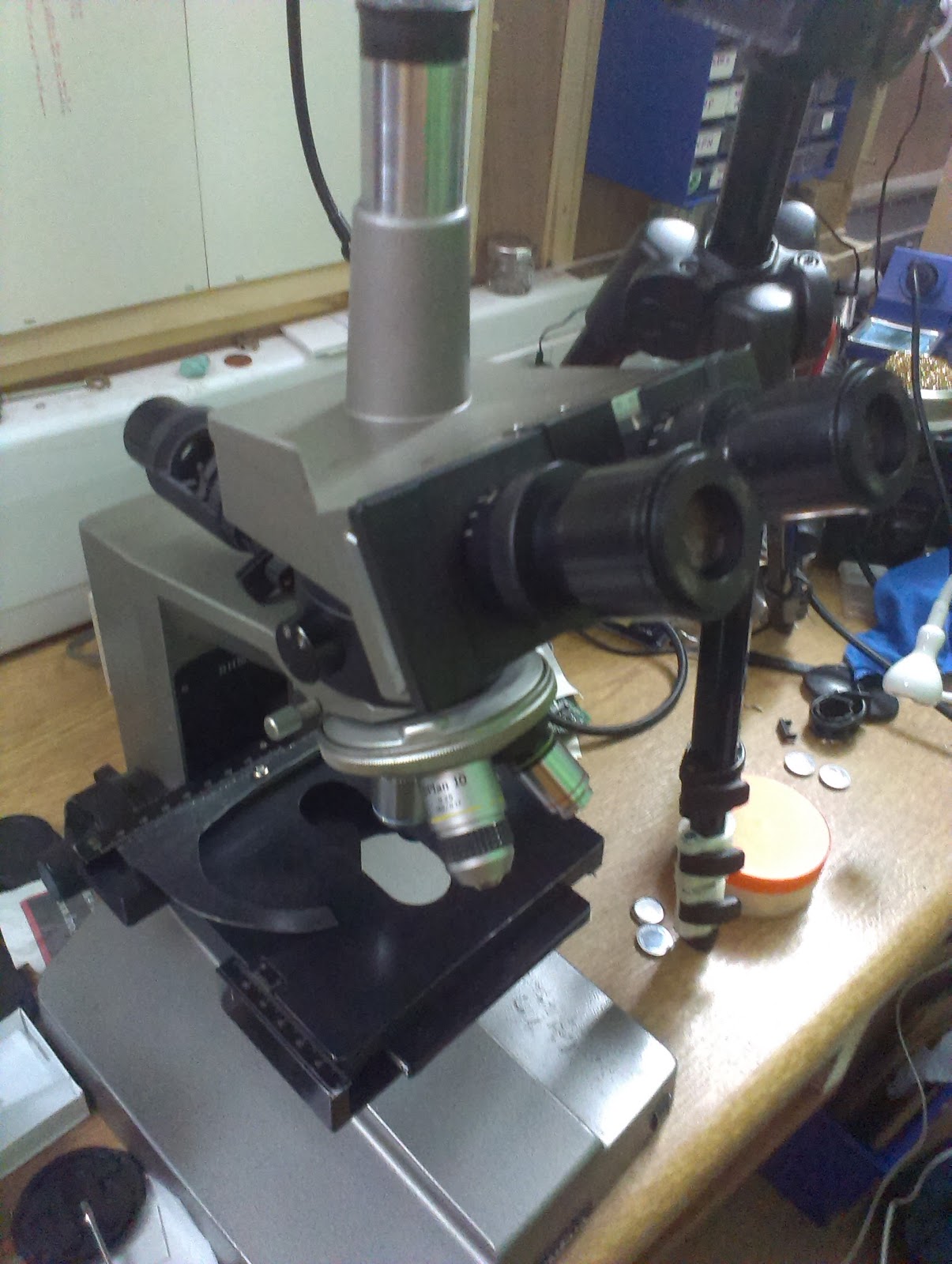
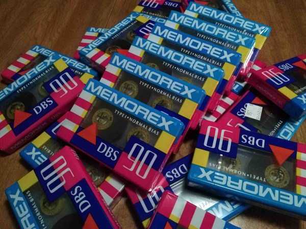
Encoding images with 5os technology is only one part of this ongoing project. Storage and playback are handled by a 90s tape deck and the display unit is a contemporary Android phone. Combining several generations in one build comes with its own set of challenges, such as getting a working audio connection between the phone and the tape deck or repairing old consumer electronics. His project logs on this topic are solid contenders for ‘Fail Of The Week’ posts. For instance, making his own belts for the cassette deck was fascinating but a dead end.

The technological breadth of the project makes it more interesting with every turn. Set some time aside this weekend for an entertaining read.

Just a couple of years back ham radio operators had the opportunity to decode SSTV beamed down from the ISS when they commemorated [Yuri Gagarin’s] birthday. Now if the mechanical part of this project is what caught your interest, you’ll also want to look back on this MIDI sampler which used multiple cassette players.

BOM Cost Optimization And Tindie Badge Engineering

For the last few months, I’ve been up to my neck in electronic conference badges. This year, I created the single most desirable badge at DEF CON. I also built a few Tindie badges, and right now I’m working on the logistics behind the Hackaday SuperConference badge. Sit tight on that last one — we’re doing something really, really special next month.

Most badge projects are one-off production runs. This is to be expected from a piece of hardware that’s only meant to be distributed at a single event. The Tindie badge is different. It’s now a thing, and we’re building multiple badges for all the cons and conferences Hackaday and Tindie are attending for the rest of the year. This means I have the opportunity to do hardware revisions on the Tindie badge. Right now I’ve built three versions of the Tindie and we’ve distributed about two thousand of these kits at DEF CON, Maker Faire New York, and the Open Hardware Summit.

After about two thousand units, I think we finally have this down. This is how I designed three versions of hardware in as many months and cut the BOM cost of each badge in half. This is bordering on a marginally impressive piece of engineering, and a great lesson on BOM cost optimization.

Continue reading “BOM Cost Optimization And Tindie Badge Engineering”

Precision Pantograph Probes PCBs

Electronic components are getting smaller and for most of us, our eyesight is getting worse. When [Kurt] started using a microscope to get a better view of his work, he realized he needed another tool to give his hands the same kind of precision. That tool didn’t exist so he built it.

The PantoProbe is a pantograph mechanism meant to guide a probe for reaching the tiny pads of his SMT components. He reports that he has no longer has any trouble differentiating pins 0.5 mm apart which is the diameter of the graphite sticks in our favorite mechanical pencils.

[Kurt] has already expanded his machine’s capability to include a holder for a high-frequency probe and even pulleys for a pick-and-place variation. There’s no mention of dual-wielding PantoProbes as micro-helping-hands but the versatility we’ve seen suggests that it is only a matter of time.

Four bar linkages are capable of some incredible feats and they’re found all around us. Enjoy one of [Kurt]’s other custom PCBs in his Plexitube Owl Clock, or let him show you to make 3D objects with a laser engraver.

Continue reading “Precision Pantograph Probes PCBs”

Over-Engineered Mailbox Flag Machined Using Under-Engineered Mini-Lathe

[Tim Nummy] used his cheap, Chinese, bench mini-lathe to make a non-terrible mailbox flag holder (YouTube video, embedded below). Tim posts videos on his channel about garage hobby projects, many of which are built using his mini-lathe, often based on suggestions from his followers. One such suggestion was to do something about his terrible mailbox flag – we’re guessing he receives a lot of old-school fan mail.

He starts off by planning the build around 1 ¼ inch aluminum bar stock, a 688 bearing, three neodymium magnets and some screws. The rest of it is a “think and plan as you go along” project, but essentially, the new holder is in three pieces. An inner piece goes inside the mail box and holds the assembly to the mail box. The middle piece holds the two magnets which act as end-stops or limits for the flags raised and lowered positions. The final, outer piece holds the flag itself, and the bearing which allows it to rotate freely.

This part also has the third magnet embedded in it to work with the other two magnets for the limits. The use of magnets is cool, but a ball catch with two detents would have worked just as well. It’s a great simple project to follow for those who want to wet their feet on lathe work. [Tim] has also posted links to all of the tools and equipment seen in the video, so check that out if anything catches your fancy.

But workshop veterans will almost certainly cringe at several places along the video. The main one that caught our eye is obviously the shaky lathe itself. It could do with a heavier workbench, proper leveling, foundation bolts or anti-vibration mounts. And from the looks of it, the tail stock isn’t any rock steady too. Although the lathe is variable speed, the chuck rpm is set too high for aluminum, and the lack of cutting fluid makes it even more troublesome. Using oil, or even some cutting fluid, while tapping would have been wise too.

We’re not sure if it’s the shaky foundation or poor feed control, but the step cut for mounting the bearing is over-sized by a whole lot more and requires a big goop of retaining compound to glue the bearing in place. But the end result works quite well, including the magnetic catches – a complex solution for a simple problem.

We’re sure our keen-eyed readers will likely spot some more issues in [Tim]’s methods, so go at it in the comments below, but please make sure to rein in the snark and keep your feedback positive.

Continue reading “Over-Engineered Mailbox Flag Machined Using Under-Engineered Mini-Lathe”

World’s Largest Telescope Stopped By LED

Earlier this year a simple indicator LED brought the Keck 1 telescope, a 370 tons mass, to a halting stop. How exactly did an LED do this? Simple: it did nothing.

As it so happens, [Andrew Cooper] was just about the leave the summit of Mauna Kea (in Hawaii) when his radio instructed him otherwise: there was an issue. Upon returning, [Andrew] was met by a room of scientists and summit supervisors. “Yeah, this was not good, why are they all looking at me? Oh, h%#*!” The rotor wasn’t moving the telescope, and “no rotator equals no science data.” After being briefed on the problem, [Andrew] got to work. Was it a mechanical issue? No: manual mode worked quite fine, also indicating that the amplifiers and limit switches are functional as well.

Jumping from chip to chip, [Andrew] came across an odd voltage: 9.36V. In the CMOS [Andrew] was investigating, this voltage should have High (15V) or Low (0v) and nowhere in between. Judging by the 9.36V [Andrew] decided to replace the driving IC. One DS3632 later, nothing had changed. Well, maybe is one of the loads pulling the line low? With only two choices, [Andrew] eliminated that possibility quickly. Likely feeling as if he was running out of proverbial rope, [Andrew] remembered something important: “the DS3236 driving this circuit is an open collector output, it needs a pull-up to go high.”

Reviewing the schematic, [Andrew] identified the DS3236’s pull-up: an LED and its current limiting resistor. While the carbon composition resistor was “armageddon proof,” [Andrew] was suspicious of the LED. “Nick, can you get me a 5k resistor from the lab?” Hold the resistor on the pins of the chip and the amplifiers immediately enabled.

[Andrew] summarizes things quite well: “yes… One of the world’s largest telescopes, 370 tons of steel and glass, was brought to a halt because of a bad indicator LED”. It stopped things by doing nothing, or rather, by not turning on.

We love it when we get troubleshooting stories, and if you share our interest in problem-solving, check out this broken power supply troubleshooting or learn what could go wrong with I2C.

Edit: Keck 1 is one of the largest optical telescopes in the world. Thanks to [Josh] for noticing our error.

Hacking A Metallurgical Microscope

[Amen] wanted to inspect ICs on the PCBs for suitability for reuse, so he bought a metallurgical microscope that illuminates from above rather than below, since it normally looks at opaque things. It has a working distance of 0.5 mm and 10 mm, which isn’t a lot of room to solder.

The microscope didn’t come with a slide tray, so [amen] found a cheap one on eBay. Needing a connector block, he melted down some food trays into an ingot, which he then milled down into a block shape, drilled, and used to attach the slide tray to the microscope.

The thing came with a manual XY table, which the operator adjusts by turning knobs. It’s fine for most basic applications but it’s also a pain for more complicated projects, like tiling together a huge photo of a die. [amen]’s currently working on a powered XY based on a DVD drive’s stepper assemblies.

If you’re looking for more microscope projects, read up on the hacked inspection microscope and a Pi Zero ‘scope we previously published.

Teletype Machine Resurrected

A teleprinter is, at its heart, an automatic typewriter.  It’s electrically controlled and has some smarts to be able to decode an incoming message and has something that will move the keys.   These printers have been in use since the late 1800’s and [AethericLtd] have refurbished an old 1930’s design and given it a bit of steampunk flair.

As is common with older mechanical devices that have been sitting for extended periods of time, the first thing this machine needed was a bath. The machine was separated into its three main parts and soaked in a degreasing solvent. The keyboard was the dirtiest, so it got an overnight soak. Since little of the mechanism was electrical, most of it could be submerged which helped with the cleaning.

The next step in the restoration was lubrication. In order to do a proper job, the manuals (which were available online) were consulted and synthetic motor oil used for lubrication. Once all the hundreds of parts were oiled, [AethericLtd] started working on the wiring. The original wiring in this machine was called Deltabeston – a type of wire by General Electric which uses asbestos insulation. To play it safe, that wire was left alone. The selector magnet required only 4 volts to pull up, but 4 volts wasn’t enough to run the machine. The power supply used was a 120 VDC, 200 mA supply through a 2 KΩ, 10 W resistor.

Once everything was back together and working, [AethericLtd] could take machine out and show it off. The website describes not only the restoration process but also the setup, how to connect to the machine and how to communicate with the machine. Great work! If you are interested in these machines, there have been a few Teleprinter projects on the site before: this one has been modified to connect to a modern modem, and this one prints out tweets.

Continue reading “Teletype Machine Resurrected”