DIY Laptop Aims For Complete Hardware Freedom

Open source software has unquestionably gone from fringe idealism to mainstream, even if the average person doesn’t really know it. From their web browser to their smartphone operating system, more people are running open source software today than at any other time in the history of computing, and the numbers are only getting bigger. While we can debate how well some companies are handling their responsibilities to the open source community, overall this is probably a lot closer to an open source utopia that many of us ever believed we’d get.

For argument’s sake, let’s say the software is settled. What’s next? Well, if we’ve got all the open source software we could ever ask for, naturally we now need to run it on open source hardware. Just like our software, we want to see how it works, we want to modify it, and to fix it ourselves if we want. These goals are precisely what [Lukas Hartmann] had in mind when he started work on Reform, the latest entry in the world of fully open source laptops.

A plate of fresh keycaps

Like the Novena that came before it, the Reform leverages the four-core ARM Cortex-A9 NXP i.MX6 SoC to deliver tablet-level performance, though [Lukas] mentions the design may migrated to the upgraded six-core version of the chip in the future which should give it a little more punch. The SoC is paired with the Vivante GC2000 GPU which can be used under Linux without any binary blobs. Most hardware is connected to the system via the USB 2.0 bus, though networking is provided by a ThinkPenguin mini PCI-e wireless adapter, and on-board SATA handles the 128 GB SSD.

While the internals are relatively run-of-the-mill these days, the work that [Lukas] has done on the case and input devices is definitely very impressive. He partnered with industrial designer [Ana Dantas] to get the look and feel of the system down, and built almost everything out of 3D printed parts. Even the keyboard caps and the trackball were manufactured in house on a Formlabs Form 2. Rather than using an off-the-shelf USB HID solution, [Lukas] is using Teensy LC boards to interface the custom input hardware with the OS.

[Lukas] is still working on how and when the Reform will be made available to the public. After some refinements, the team hopes to make both kits and individual parts available, and of course put all the files up so you can build your own if you’ve got the equipment. A mockup Amazon listing for the Reform has been posted to get the public’s feedback on the look and features of the machine, and [Lukas] asks that anyone with comments and suggestions send him an email.

Between the Reform, Novena, and the Olimex, competition in the realm of DIY laptops is frankly staggering. Now we just need more people working on open hardware smartphones.

Thanks to [Adrian] for the tip.

FruitNanny: The Raspberry Pi Baby Monitor For Geeks

Having a child is perhaps the greatest “hack” a human can perform. There’s no soldering iron, no Arduino (we hope), but in the end, you’ve managed to help create the most complex piece of machinery in the known galaxy. The joys of having a child are of course not lost on the geekier of our citizens, for they wonder the same things that all new parents do: how do we make sure the baby is comfortable, how many IR LEDs do we need to see her in the dark, and of course the age old question, should we do this with a web app or go native?

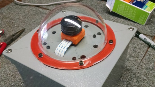
If you’re the kind of person who was frustrated to see that “What to Expect When You’re Expecting” didn’t even bother to mention streaming video codecs, then you’ll love FruitNanny, the wonderfully over-engineered baby monitor created by [Dmitry Ivanov]. The product of nearly two years of development, FruitNanny started as little more than a Raspberry Pi 1n a plastic lunch box. But as [Dmitry] details in his extensive write-up, the latest iteration could easily go head-to-head with products on the commercial market.

[Dmitry] gives a full bill of materials on his page, but all the usual suspects are here. A Raspberry Pi 3 paired with the official NoIR camera make up the heart of the system, and the extremely popular DHT22 handles the environmental monitoring. A very nice 3D printed case, a lens intended for the iPhone, and a dozen IR LEDs round out the build.

The software side is where the project really kicks into high gear. Reading through the setup instructions [Dmitry] has provided is basically a crash course in platform-agnostic video streaming. Even if a little bundle of joy isn’t on your development roadmap, there’s probably a tip or two you can pick up for your next project that requires remote monitoring.

It probably won’t surprise you that geeky parents have been coming up with ways to spy on their kids for some time now, and if you can believe it, some don’t even include a Raspberry Pi.

Look What Came Out Of My USB Charger !

Quick Charge, Qualcomm’s power delivery over USB technology, was introduced in 2013 and has evolved over several versions offering increasing levels of power transfer. The current version — QCv3.0 — offers 18 W power at voltage levels between 3.6 V to 20 V.  Moreover, connected devices can negotiate and request any voltage between these two limits in 200 mV steps. After some tinkering, [Vincent Deconinck] succeeded in turning a Quick Charge 3.0 charger into a variable voltage power supply.

His blog post is a great introduction and walk through of the Quick Charge ecosystem. [Vincent] was motivated after reading about [Septillion] and [Hugatry]’s work on coaxing a QCv2.0 charger into a variable voltage source which could output either 5 V, 9 V or 12 V. He built upon their work and added QCv3.0 features to create a new QC3Control library.

To come to grips with what happens under the hood, he first obtained several QC2 and QC3 chargers, hooked them up to an Arduino, and ran the QC2Control library to see how they respond. There were some unexpected results; every time a 5 V handshake request was exchanged during QC mode, the chargers reset, their outputs dropped to 0 V and then settled back to a fixed 5 V output. After that, a fresh handshake was needed to revert to QC mode. Digging deeper, he learned that the Quick Charge system relies on specific control voltages being detected on the D+ and D- terminals of the USB port to determine mode and output voltage. These control voltages are generated using resistor networks connected to the microcontroller GPIO pins. After building a fresh resistor network designed to more closely produce the recommended control voltages, and then optimizing it further to use just two micro-controller pins, he was able to get it to work as expected. Armed with all of this information, he then proceeded to design the QC3Control library, available for download on GitHub.

Thanks to his new library and a dual output QC3 charger, he was able to generate the Jolly Wrencher on his Rigol, by getting the Arduino to quickly make voltage change requests.

Continue reading “Look What Came Out Of My USB Charger !”

3D Printed Gear Serves Seven Months Hard Labor

Even the staunchest 3D printing supporter would have to concede that in general, the greatest strength of 3D printing is not in the production of final parts, but in prototyping. Sure you can make functional prints, as the pages of this site will attest; but few would argue that you wouldn’t be better off getting your design cut out of metal or injection molded if you planned on putting the part into service over the long term. Especially if the part was to be subjected to rough service in an industrial setting.

While that’s valid advice, it certainly isn’t the definitive word on the issue. Just because a part is printed in plastic on a desktop 3D printer doesn’t necessarily mean it can’t be put into real service, at least for as long as it takes to get proper replacement parts. A recent success story from [bloomautomatic] serves as a perfect example, when one of the gears in his MIG welder split, he decided to try and print up a replacement in PLA while he waited for the nylon gear to get shipped out to him. Fast forward seven months and approximately 80,000 welds later, and [bloomautomatic] reports it’s finally time to install those replacement gears he ordered.

In the pictures [bloomautomatic] posted you can see the printed gear finally wore down to the point the teeth were essentially gone where they meshed with their metal counterparts. To those wondering why the gear was plastic to begin with, [bloomautomatic] explains that it’s intended to be a sacrificial gear that will give way instead of destroying the entire gearbox in the event of a jam. According to the original post he made when he installed the replacement gear, the part was printed in Folgertech PLA on a Monoprice Select Mini. There’s no mention of infill percentage, but with such a small part most slicers would likely have made it essentially solid to begin with.

While surviving seven tortuous months inside of the welder is no small feat, we wonder if hardier PLA formulationstreatment of the part post-printing, or even casting it in a different material couldn’t have turned this temporary part into a permanent replacement.

Supercon Badge Hacking Quick-Start

The hardware badge Mike Harrison designed for this year’s Hackaday Superconference is begging to be hacked. Today, I wanted to help get you up and running quickly.

The Hacker Village atmosphere of Supercon is starting up a day early this year. On Friday, November 10th badge pick-up starts at noon and badge hacking continues throughout the afternoon, followed by a party at Supplyframe HQ that evening. Plan to get to town on Friday and join in the fun. Of course, you need to grab a Supercon ticket if you haven’t already.

Check out the 2017 Superconference Badge project page for full documentation that Mike has put together during his development process.

Continue reading “Supercon Badge Hacking Quick-Start”

Cheap RC Truck Mod Is Slightly Risky Fun

The world of RC can be neatly split into two separate groups: models and toys. The RC models are generally big, complex, and as you’d imagine, more expensive. On the other hand, the RC toys are cheap and readily available. While not as powerful or capable as their more expensive siblings, they can often be a lot of fun; especially since the lower costs means a crash doesn’t put too big of a ding into to your wallet.

With his latest mod, [PoppaFixIt] has attempted to bridge the gap between toy and model by sticking a considerably overpowered battery into a $10 RC truck from Amazon. He reports greatly improved performance from his hacked together truck, but anyone looking to replicate his work should understand the risks before attempting to hack up their own version.

The principle is pretty simple; the truck is designed to run on two AA batteries, providing 3 volts. But by swapping the AAs out for a 3.7 volt 1S LiPo of the type that’s used in small airplanes and quadcopters, you can get an instant boost in power. As a happy side effect, the LiPo batteries are also rechargeable and fairly cheap, so you won’t have to keep burning through alkaline AAs.


The mod itself is a basic job that only requires a few bucks in parts, and for which [PoppaFixIt] has helpfully provided Amazon links. Essentially you just crack open the truck, solder a JST connector pigtail to the positive and negative traces on the PCB, and then pop a hole in the roof to run the new battery wires out.

Right about now the RC purists are probably screaming obscenities at their displays, and not without reason. As fun as these supercharged little trucks are to drive, there are a number of real issues here which need to be mentioned.

First, while the motor will probably be alright with a bit higher voltage running through them, the gears won’t be liking it one bit. In fact, [PoppaFixIt] even mentions they shredded a few gears when they tried to take one off-road. The second issue is that since these vehicles were not designed with LiPo batteries in mind, there’s no low voltage cutoff to prevent over discharge. If you aren’t careful, a setup like this will cook those cute little batteries in short order. But hey, at least it’s all cheap.

If you are more interested in control than power, you may want to check out the previous hacks we’ve featured. Seems like these little RC trucks are the platform of choice for hackers who want to get stuff moving on the cheap.

Why Not Expose Your PCBs Through An LCD?

Most people who have dabbled in the world of electronic construction will be familiar in some form with the process of producing a printed circuit board by exposing a UV sensitive coating through a transparent mask, before moving on to etching. Older readers will have created their masks by hand with crêpe paper tape on acetate, while perhaps younger ones started by laser-printing from their CAD package.

How about a refinement of the process, one which does away with the acetate mask entirely? [Ionel Ciobanuc] may have the answer, in the form of an exposure through an LCD screen. The video below the break shows how it’s done, starting with a (probably a bit too lengthy) sequence on applying the photo-resist coating to the board, and then sitting LCD on top of UV lamp with the board positioned at the top of the pile.

It’s an interesting demonstration, and one that certainly removes a step in the process of PCB creation as it brings the pattern direct from computer to board without an intermediate. Whether or not it’s worth the expenditure on an LCD is up to you, after all a sheet of acetate is pretty cheap and if you already have a laser printer you’re good to go. We’re curious to know whether or not any plastic components in the LCD itself might be damaged by long-term exposure to intense UV light.

Continue reading “Why Not Expose Your PCBs Through An LCD?”