If there’s one thing that amateur radio operators are passionate about, it’s the search for the perfect sine wave. Oscillators without any harmonics are an important part of spectrum hygiene, and while building a perfect oscillator with no distortion is a practical impossibility, this twin-tee audio frequency oscillator gets pretty close.
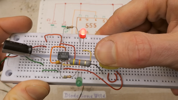
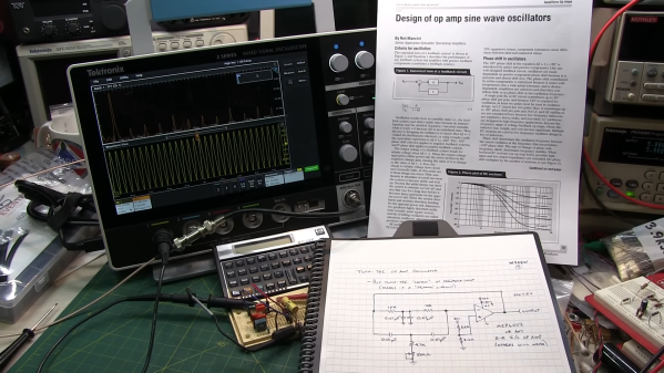
As [Alan Wolke (W2AEW)] explains, a twin-tee oscillator is quite simple in concept, and pretty simple to build too. It uses a twin-tee filter, which is just a low-pass RC filter in parallel with a high-pass RC filter. No inductors are required, which helps with low-frequency designs like this, which would call for bulky coils. His component value selections form an impressively sharp 1.6-kHz notch filter about 40 dB deep. He then plugs the notch filter into the feedback loop of an MCP6002 op-amp, which creates a high-impedance path at anything other than the notch filter frequency. The resulting sine wave is a thing of beauty, showing very little distortion on an FFT plot. Even on the total harmonic distortion meter, the oscillator performs, with a THD of only 0.125%.
This video is part of [Alan]’s “Circuit Fun” series, which we’ve really been enjoying. The way he breaks complex topics into simple steps that are easy to understand and then strings them all together has been quite valuable. We’ve covered tons of his stuff, everything from the basics of diodes to time-domain reflectometry.
Continue reading “No Inductors Needed For This Simple, Clean Twin-Tee Oscillator”