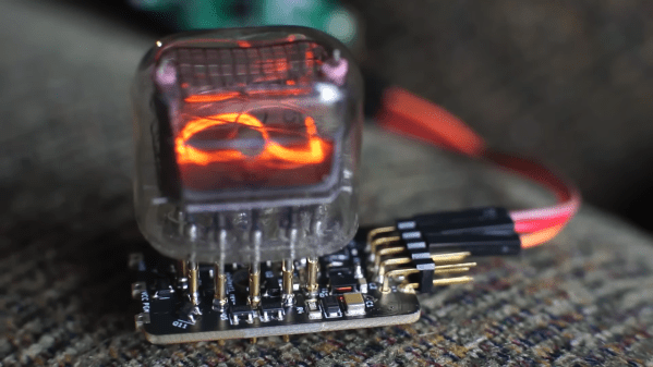
Intel RealSense D435 Depth Camera

RealSense No Longer Makes Sense For Intel

We love depth-sensing cameras and every neat hack they enabled, but this technological novelty has yet to break through to high volume commercial success. So it was sad but not surprising when CRN reported that Intel has decided to wind down their RealSense product line.

As of this writing, one of the better confirmations for this report can be found on the RealSense SDK GitHub repository README. The good news is that core depth-sensing RealSense products will continue business as usual for the foreseeable future, balanced by the bad news that some interesting offshoots (facial authentication, motion tracking) will be declared “End of Life” immediately and phased out over the next six months.

This information tells us while those living out on the bleeding edge will have to scramble, there is no immediate crisis for everyone else, whether they be researchers, hobbyists, or product planners. But this also means there will be no future RealSense cameras, kicking off many “What’s Next?” discussions in various communities. Like this thread on ROS (Robot Operating System) Discourse.

Three popular alternatives offer distinctly different tradeoffs. The “Been Around The Block” name is Occipital, with their more expensive Structure Pro sensor. The “Old Name, New Face” option is Microsoft Azure Kinect, the latest non-gaming-focused successor to the gaming peripheral that started it all. And let’s not forget OAK-D as the “New Kid On The Block” that started with a crowdfunding campaign and building an user community by doing things like holding contests. Each of these will appeal to a different niche, and we’ll keep our eye open in the future. Let’s see if any of them find the success that eluded the original Kinect, Google’s Tango, and now Intel’s RealSense.

[via Engadget]

flow IO module options

Get Your Flex On With The FlowIO Platform

Hackaday Prize 2021 entry FlowIO Platform promises to be to pneumatics what Arduino is to Electronics. The modular platform comprises a common controller/valve block, a selection of differently sized pumps, and a few optional connectivity and sensing blocks. With Arduino software support as well as as Javascript and web-GUI, there’s a way to program this no matter what the level of experience the user has.

flowIO exploded view
flowIO exploded view from http://www.softrobotics.io/flowio

This last point is a critical one for the mission [Ali Shtarbanov] from the MIT Media Lab is setting out for this project. He reminds us that in decades gone by, there was a significant barrier to entry for anyone building electronics prototypes. Information about how to get started was also much harder to by before the internet really got into gear.

It’s a similar story for software, with tools like Scratch and Python lowering the barrier to entry and allowing more people to get their toes wet and build some confidence.

But despite some earlier work by projects like the Soft Robotics Toolkit and Programmable-Air, making a start on lowering the bar for pneumatics support for soft robotics, and related applications, the project author still finds areas for further improvement. FlowIO was designed from the ground-up to be wearable. It appears to be much smaller, more portable and supports more air ports and a greater array of sensing and connectivity than previous Open Source work to date.

Creative Commons Hardware

Whilst you can take all the plans (free account signup required) and build yourself a FlowIO rig of your very own, the project author offers another solution. Following on from the Wikipedia model of free sharing and distribution of information, FlowIO offers its hardware for free, for the common good. Supported by donations to the project, more hardware is produced and distributed to those who need it. The only ask is that redundant kits are passed on or returned to base for upgrade, rather than landfill.

Continue reading “Get Your Flex On With The FlowIO Platform”

DIY Source Measurement Unit

DIY Source Measurement Unit Shows All The Details

An SMU or Source Measurement Unit works a bit like a power supply, in that it can source current into a load and a bit like an electronic load, in that it can sink current from a power source. It includes a crossover circuit, so that it cleanly and predictably swaps between sink and source modes automatically. This makes it terribly useful for testing all manner of power circuits, charging and characterizing batteries or just saving bench space by replacing two separate boxes.

This DIY-SMU from analog electronics guru [Dave Erikson] is a full four-quadrant design, meaning that it can operate with both positive and negative voltages. The design shows excellent performance, comparable to commercial instruments that cost serious money, which is testament to [Dave]’s skill and experience.

Source: Wikipedia

The quadrants can be understood if you imagine a graph with voltage on the horizontal axis, and current on the vertical. Both axes can swing to both polarities, with quadrants I & III indicating power delivered into a load and quadrants II & IV power absorbed from a source.

The very detailed project logs show every gory detail, every problem found and the work to solve it. Its a long read, which for those interested in such devices, will be time well spent in this scribe’s humble opinion.

The DIY-SMU is mostly analog in nature, with the control portion courtesy of a Teensy 3.2, with a Nextion TFT display with touch for the user interface. The firmware even supports SCPI over USB to allow remote control and data gathering, so its ready to drop right into your test and measurement stack. For more reading goodness, checkout JSMU, a related project, taking inspiration from the DIY-SMU. Details can be found on this project GitHub repo.

Many power supply projects have graced these pages over the years, like this 2015 Hackaday Prize Entry but this is one of the few four-quadrant designs to be found, so hats off!

Continue reading “DIY Source Measurement Unit Shows All The Details”

Valve Sells Software, So What’s With All The Hardware?

Steam branding is strong. Valve Corporation has turned their third-party marketplace into the first place millions choose to buy their PC games. The service has seen record-breaking numbers earlier this year with over 25 million concurrent users, so whatever they are doing is clearly working. Yet with all those software sales, last month Valve announced a new piece of hardware they call the Steam Deck.

Use the colloquialism you’d like, “not resting on your laurels” or “Mamba Mentality”, it’s not as if competitors in the handheld PC space are boasting ludicrous sales numbers. At their core, Valve is in the business of selling computer games. So why venture into making hardware? Continue reading “Valve Sells Software, So What’s With All The Hardware?”

Solving Ultra High Vacuum Leaks Has An Elementary Solution

When we think of a vacuum leak we generally think of a car that just doesn’t want to run quite right. Most normally aspirated internal combustion engines rely on the vacuum created by the pistons to draw in the air fuel mixture that’s produced by the carburetor or fuel injection system. Identifying the leak usually involves spraying something combustible around common trouble areas while the engine is running. Changes to the engine speed indicate when the combustible gas enters the intake manifold and the leak can be found.

What if your vacuum leak is in a highly specialized piece of scientific equipment where the pressures are about 12 times orders of magnitude lower than atmospheric pressure, and the leak is so small it’s only letting a few atoms into the vacuum chamber at a time? [AlphaPhoenix] takes dives deep into this very subject in his video “Air-tight vs. Vacuum-tight.” which you can watch below the break.

Not only does [AlphaPhoenix] discuss how a perfect pressure vessel is sealed, he also explains the specialized troubleshooting methods used which turn out not to be all that different from troubleshooting an automotive vacuum leak- only in this case, several magnitudes more complex and elemental in nature.

We also enjoyed the comments section, where [AlphaPhoenix] addresses some of the most common questions surrounding the video: Torque patterns, the scarcity of the gasses used, and leaving well enough alone.

Does talking about vacuums get you pumped? Perhaps you’d enjoy such vacuum hacks as putting the toothpaste back in the tube in your homemade vacuum chamber.

Thank you [Morgan] for sending this one in. Be sure to send in your own hacks, projects, and fantastic finds through the Tip Line!

Continue reading “Solving Ultra High Vacuum Leaks Has An Elementary Solution”

The Zeloof Z2 Intergrated Circuit Has 100 Transistors

Back in 2018 we reported on the first silicon integrated circuit to be produced in a homemade chip fab. It was the work of [Sam Zeloof], and his Z1 chip was a modest six-transistor amplifier. Not one to rest on his laurels, he’s back with another chip, this time the Z2 is a hundred-transistor array. The Z2 occupies about a quarter of the area of the previous chip and uses a 10µm polysilicon gate process as opposed to the Z1’s metal gates. It won’t solve the global chip shortage, but this is a major step forward for anyone interested in building their own semiconductors.

The transistors themselves are FETs, and [Sam] is pleased with their consistency and characteristics. He’s not measured his yield on all samples, but of the twelve chips made he says he has one fully functional chip and a few others with at least 80% functionality. The surprise is that his process is less complex than one might expect, which he attributes to careful selection of a wafer pre-treated with the appropriate oxide layer.

You can see more about the Z2 in the video below the break. Meanwhile, should you wish to learn more about the Z1 you can see [Sam’s] Hackaday Superconference talk on the subject. We’re looking forward to the Z3 when it eventually arrives, with bated breath!

Continue reading “The Zeloof Z2 Intergrated Circuit Has 100 Transistors”

Hacked IKEA Air Quality Sensor Gets Custom PCB

Last month we brought word of the IKEA VINDRIKTNING, a $12 USD air quality sensor that could easily be upgraded to log data over the network with the addition of an ESP8266. It only took a couple of wires soldered to the original PCB, and since there was so much free space inside the enclosure, you didn’t even have to worry about fitting the parasitic microcontroller; just tape it to the inside of the case and button it back up.

Now we’ve got nothing against the quick and dirty method around these parts, but if you’re looking for a slightly more tidy VINDRIKTNING modification, then check out this custom PCB designed by [lond]. This ESP-12F board features a AP2202 voltage regulator, Molex PicoBlade connectors, and a clever design that lets it slip right into a free area inside the sensor’s case. The project description says the finished product looks like it was installed from the factory, and we’re inclined to agree.

Nothing has changed on the software side, in fact, the ESP-12F gets flashed with the same firmware [Sören Beye] wrote for the Wemos D1 Mini used in his original modification. That said [lond] designed the circuit so the MCU can be easily reprogrammed with an FTDI cable, so just because you’re leaving the development board behind doesn’t mean you can’t continue to experiment with different firmware builds.

It’s always gratifying to see this kind of community development, whether or not it was intentionally organized. [lond] saw an interesting idea, found a way to improve its execution, and released the result out into the wild for others to benefit from. It wouldn’t be much of a stretch to say that this is exactly the kind of thing Hackaday is here to promote and facilitate, so if you ever find yourself inspired to take on a project by something you saw on these pages, be sure to drop us a line.