At this point, we’ve seen more Raspberry Pi Network Attached Storage (NAS) builds than we can possibly count. The platform was never a particularly ideal choice for this task due to the fact it could only connect to drives over USB, but it was cheap and easy to work with, so folks made the best of it. But that all changed once the Compute Module 4 introduced PCIe support to the Raspberry Pi ecosystem.
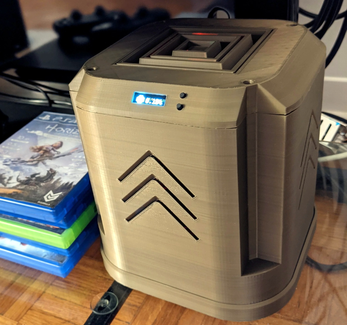
If this impressive NAS built by [mebs] represents the shape of things to come, we’re more than a little excited. On the outside, with its 3D printed case and integrated OLED display to show system status, it might look like plenty of builds that came before it. But pop the top of this cyberpunk-styled server, and you realize just how much work went into it.
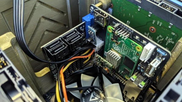
 At the heart of this NAS is a purpose-built carrier board that [mebs] designed based on the KiCad files the Raspberry Pi Foundation released for their official CM4 IO Board. While not much larger than the CM4 itself, the NAS board breaks out the board’s PCIe, Ethernet, HDMI, and USB. There’s also a header for I2C, used primarily for the OLED display but naturally expandable to additional sensors or devices, and nine GPIO pins for good measure.
Of course, that alone doesn’t make a NAS. Into that PCIe port goes a four channel SATA controller card, which in turn is connected to the hard disk drives that are nestled into their respective nodes of the printed case. A central fan blows over the electronics at the core, and thanks to clever design and a few cardboard seals, pulls air over the drives by way of intake vents printed into the sides.
As impressive as this build is, not everyone will need this level of performance. If you don’t mind being limited to USB speeds, you can 3D print a NAS enclosure for the standard Raspberry Pi. Or you could always repurpose an old PC case if you’d like something a bit more substantial.