We are used to flipdots, single mechanical pixels that are brightly colored on one side and black on the other, flipped over by a magnetic field. Driving the little electromagnets that make them work is a regular challenge in our community. [Johan] however has a new take on the flipdot, and it’s one we’ve never seen before. Instead of making a magnetic field to flip his dots he’s doing without the electronics entirely, and just using a magnet.
The project is a level indicator for a water tank, which contains a magnet floating in a plastic bottle. This has previously been used to trigger a reed switch that controls the refill pump. To those reed switches he adds a row of flipdots, but these aren’t the commercial dots you might once have seen adorning the front of your local bus. Instead, they’re custom dots made from washers, suspended in pivots by means of a spot weld and mounted in a frame inside a clear tube to keep dirt at bay. As you can see in the video below the break, when the magnet floats past inside the tank it flips them over one way, and on its return journey if flips them back the other. The result is a fully serviceable flipdot display, completely lacking the normal electronics, and we rather like it.
(It may be the first electronic-free flipdot we’ve shown you, but it’s not the first homemade one.)
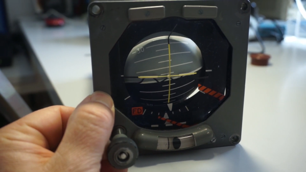
Aviation instruments are highly interesting pieces of engineering, and it is quite satisfying to watch the often over-engineered mechanisms behind them. If you are into that sort of thing it is worthwhile to check out [Erik Baigar]’s video where he explains the working principle of the attitude indicator from a Tornado jet.
The attitude indicator or artificial horizon of an airplane is one of the most important instruments, especially during poor sight. The ADI42-124 used in the Tornado jet is completely standalone and only needs a DC power supply which is why [Erik Baigar] can show it off while standing on his balcony. At the heart of this instrument is a gyroscope which consists of a spinning disc attached to a gimbal mount. Due to the conservation of angular momentum, the spin axis will always keep its orientation when the instrument is rotated. However, mechanical gyroscopes tend to drift over time and therefore include a mechanism to keep the spin axis upright with respect to the direction of gravity. The ADI42-124 uses an entirely mechanical mechanism for this based on free swiveling weights. Forget everything we said earlier about overengineering as [Erik Baigar] also uncovers a fatal design flaw which leads to the instrument’s self-destruction as shown in the picture here. Unfortunately, this will render most of the units you can buy on eBay useless.
Be sure to check out [Erik Baigar]’s webpage which is nerd paradise for vintage computer and avionics fans or watch another gyroscope teardown.
Test and programming fixtures are great time-savers for anyone who needs to deal with more than a handful of PCBs. Instead of plugging in connectors (or awkwardly holding probe tips or wires) to program some firmware or run tests, one simply pops a PCB into a custom fixture with one hand, and sips a margarita with the other while a program decides whether everything is as it should be. Test fixtures tend to be custom-made for specific board layouts, meaning one tester is needed per board or device type, but this work is easily justified by the huge time savings they offer.
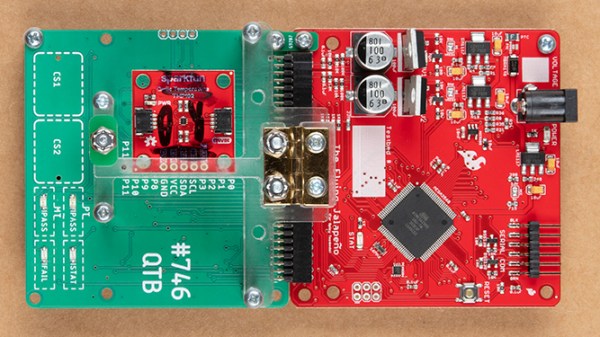
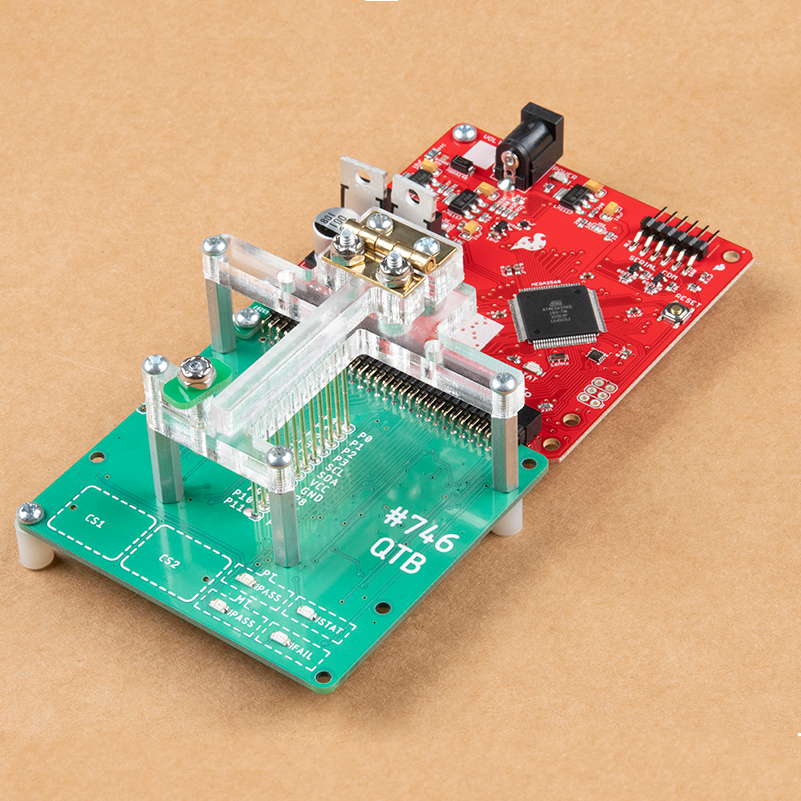
An inserted PCB sits atop the thick acrylic piece, with pogo pins making contact from below. Generous space on the left and right make sure there is clearance for any mounted components. Visible near the bottom of the green board are output LEDs, and two touch-sensitive pads.
The test unit looks like pretty familiar stuff at first glance: some hardware responsible for running the test program, laser-cut acrylic jig to hold a test PCB in a consistent position, spring-loaded pogo pins to make temporary electrical connections, and LEDs to clearly indicate PASS and FAIL states. The clever part is the way the fixture is designed to accommodate multiple board designs, and how it uses several 74LVC4066 quad bilateral switch ICs to take care of switching which pogo pins are connected and to where.
As mentioned, to be compatible with multiple boards there must be common design elements to exploit. In Sparkfun’s case, the through-hole connections on their breakout boards are all in a row with standard 0.1″ spacing. By using the aforementioned pogo pins and 4066 ICs, different pinouts can be accommodated and multiple board types can be used without any need to swap to different test hardware.
Earlier this month, we posted coverage of an ingenious calculator hack that took a Casio calculator and put an ESP8266 module and an OLED display in the space occupied by its solar cell. Controlled by a pair of unobtrusive Hall effect devices, the calculator could have been used as an ingenious cheating device but was to us the epitome of a well-executed hack. We may have liked it but it seems the folks at Casio didn’t, because they’ve issued a DMCA takedown notice for the project’s GitHub repository.
This is a picture of Barbra Streisand, who might almost be the patron saint of unintended consequences. Unknown author / Public domain.
We’re not lawyers, but if you’d care to visit our original coverage and watch the video in full, you’ll see that the ESP does not in any way tap into the calculator’s functions. The epoxy blob over the Casio processor is intact and no wires connect to the calculator mainboard, so it is difficult to imagine how any Casio code could have found its way into a repository full of ESP8266 code for the Arduino IDE. A quick search for “Hack-Casio-Calculator” on GitHub, at the time of publishing, turned up the relevant code despite Casio’s takedown, and we can’t see what they’re on about. Maybe you can?
Over the years there have been many attempts to use the DMCA on projects in our community. Some have been legitimate, others have been attempts to suppress exposure of woeful security, and still more have been laughably absurd. This one seems to us to edge into the final category, because it is difficult to see how the project described could contain any Casio code at all. It would be entirely legitimate to issue a DMCA takedown had the epoxy blob been removed and Casio’s code been retrieved from the calculator chip (and we’d certainly cover that story!), but as far as we can see taking a scalpel to a calculator’s case and stuffing a module behind the solar panel window does not come close.
It’s evident that Casio do not like the idea of one of their calculators being turned into a cheating device, and we understand why that might be the case. But to take the DMCA route has served only to bring more publicity to the affair, and those of us with long memories know that this can only lead to one conclusion.
Most modern equipment is connected over USB, and generally speaking we’re all the better for it. But that’s not to say there aren’t some advantages to using serial and parallel ports. For example, the slower and less complex protocols can be a bit easier to debug when devices aren’t communicating, which [Jeremy Cook] demonstrates in his latest project.
Looking to troubleshoot some communications problems he was having between his computer and CNC router, [Jeremy] came up with a handy little gadget that will allow him to visualize data passing through each pin of the parallel port in real-time. Even from across the room he can tell at a glance if communication is active, and with a keen eye, determine if he’s getting bi-directional traffic or not.
From a technical standpoint, this is a pretty simple project. The custom PCB is essentially just a pass-through, with an array of 3 mm LEDs and matching 10K resistors hanging off the data lines. But [Jeremy] found it to be an excellent excuse to brush up his KiCad skills. As he explains in the video after the break, this project certainly won’t impress the folks that do PCB design on a daily basis; but if you’re still learning the ropes, these are precisely the kind of projects you should be looking for.
Before any of you say it in the comments, we already know devices like this are available commercially for a few bucks. But that’s hardly the point. Things would be awfully slow around these parts if we disregarded any project that had a commercial alternative.
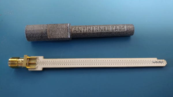
If you do any work with high-speed signals, you quickly realize that probing is an art unto itself. Just having a fast oscilloscope isn’t enough; you’ve got to have probes fast enough to handle the signals you want to see. In this realm, just any old probe won’t do: the input capacitance of the classic RC probe you so often see on low-bandwidth scopes starts to severely load down a circuit well below 1 GHz. That’s why we were really pleased to see [Andrew Zonenberg’s] new open-source design for a 2 GHz resistive probe hit Kickstarter.
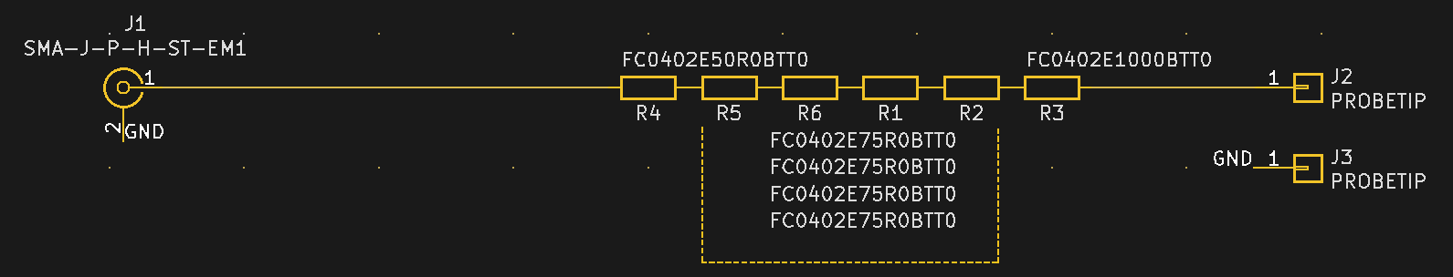
The design of this new probe looks deceptively simple. Known as a Z0-probe, transmission-line probe, or resistive probe, the circuit works as a voltage divider, created from the 50-Ohm input impedance of a high-speed oscilloscope input and an external resistor, to reduce loading on the circuit-under-test. In this case, the input resistance has been chosen to be 500 Ohms, yielding a 10x probe. In theory, building such a probe is as simple as soldering a resistor to the end of a piece of coaxial cable. You can do exactly that, but in practice, optimizing a design is much more complex. As you can see in the schematic, just choosing a resistor of the right value doesn’t cut it at these frequencies. Even the tiny 0402-size resistors have parasitic capacitance and inductance that affect the response, and choosing a combination of parts that add to the correct resistance but reduce the overall capacitive loading makes a huge difference.
2 GHz Passive Probe Schematic
Don’t be fooled: the relatively simple schematic belies the complexity of such a design. At these speeds, the PCB layout is just as much of a component as the resistors themselves, and getting the transmission-line and especially the SMA footprint launch correct is no easy task. Using a combination of modeling with the Sonnet EM simulator and empirical testing, [Andrew] has ended up with a design that’s flat (+/- 1 dB) out to 1.98 GHz, with a 10-90% rise time of 161 ps. That’s a fast probe.
The probe comes in a few options, from fully assembled with traceable specs to a DIY solder-it-yourself version. You probably know which of these options you need.
We really like to see this kind of knowledge and thoroughness go into a project, and we’d love to see the Kickstarter project reach its goals, but perhaps the best part is that the design is permissively open-source licensed. This is a case where having the board layout open-sourced is key; the schematic tells you maybe half of what’s really going on in the circuit, and getting the PCB right yourself can be a long and frustrating exercise. So, have a look at the project, and if you haven’t got probes suitable for your fastest scopes, build one, or better yet, support the development of this exciting design.
The Valve Index VR headset incorporates a number of innovations, one of which is the distinctive off-ear speakers instead of headphones or earbuds. [Emily Ridgway] of Valve shared the design and evolution of this unusual system in a deep dive into the elements of the Index headset. [Emily] explains exactly what they were trying to achieve, how they determined what was and wasn’t important to deliver good sound in a VR environment, and what they were able to accomplish.
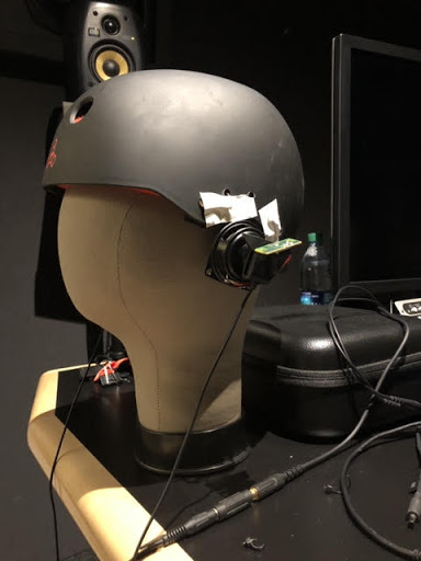
First prototype, a proof-of-concept that validated the basic idea and benefits of off-ear audio delivery.
Early research showed that audio was extremely important to providing a person with a good sense of immersion in a VR environment, but delivering a VR-optimized audio experience involved quite a few interesting problems that were not solved with the usual solutions of headphones or earbuds. Headphones and earbuds are optimized to deliver music and entertainment sounds, and it turns out that these aren’t quite up to delivering on everything Valve determined was important in VR.
The human brain is extremely good at using subtle cues to determine whether sounds are “real” or not, and all kinds of details come into play. For example, one’s ear shape, head shape, and facial geometry all add a specific tonal signature to incoming sounds that the brain expects to encounter. It not only helps to localize sounds, but the brain uses their presence (or absence) in deciding how “real” sounds are. Using ear buds to deliver sound directly into ear canals bypasses much of this, and the brain more readily treats such sounds as “not real” or even seeming to come from within one’s head, even if the sound itself — such as footsteps behind one’s back — is physically simulated with a high degree of accuracy. This and other issues were the focus of multiple prototypes and plenty of testing. Interestingly, good audio for VR is not all about being as natural as possible. For example, low frequencies do not occur very often in nature, but good bass is critical to delivering a sense of scale and impact, and plucking emotional strings.
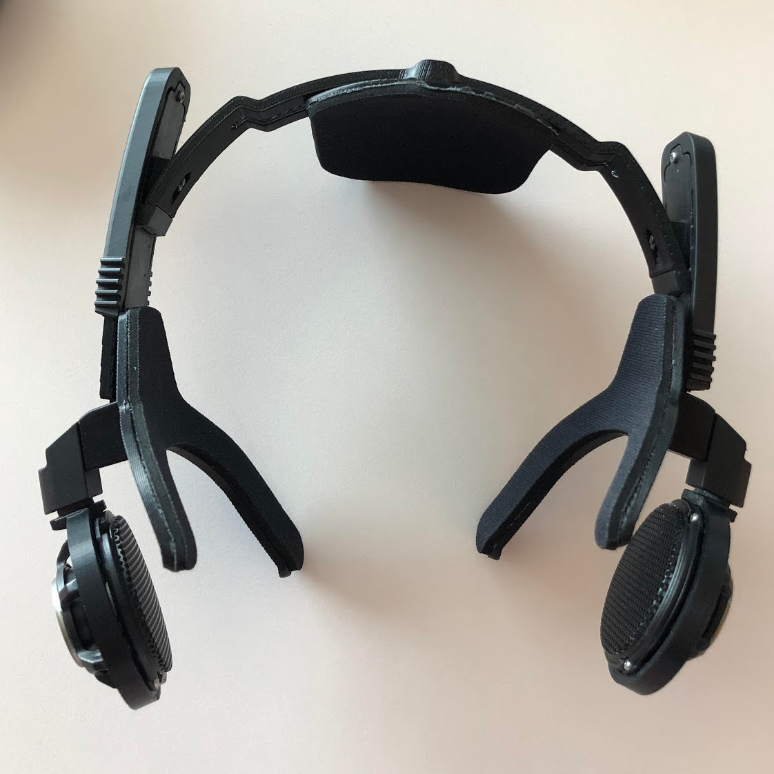
“Hummingbird” prototype using BMR drivers. Over twenty were made and lent to colleagues to test at home. No one wanted to give them back.
The first prototype demonstrated the value of testing a concept as early as possible, and it wasn’t anything fancy. Two small speakers mounted on a skateboard helmet validated the idea of off-ear audio delivery. It wasn’t perfect: the speakers were too heavy, too big, too sensitive to variation in placement, and had poor bass response. But the results were positive enough to warrant more work.
In the end, what ended up in the Index headset is a system that leans heavily on Balanced Mode Radiator (BMR) speaker design. Cambridge Audio has a short and sweet description of how BMR works; it can be thought of as a hybrid between a traditional pistonic speaker drivers and flat-panel speakers, and the final design was able to deliver on all the truly important parts of delivering immersive VR audio in a room-scale environment.
As anyone familiar with engineering and design knows, everything is a tradeoff, and that fact is probably most apparent in cutting-edge technologies. For example, when Valve did a deep dive into field of view (FOV) in head-mounted displays, we saw just how complex balancing different features and tradeoffs could be.