We’re truly fortunate to have so many incredible open source projects floating around on the Internet, since there’s almost always some prior art you can lean on. By combining bits and pieces from different projects, you can often save yourself a huge amount of time and effort. It’s just a matter of figuring out how all the pieces fit together, like in this clever mash-up by [bethiboothi] that takes advantage of the fact that the popular TP4056 lithium-ion battery charger module happens to be almost the exact same size of the ESP-01.
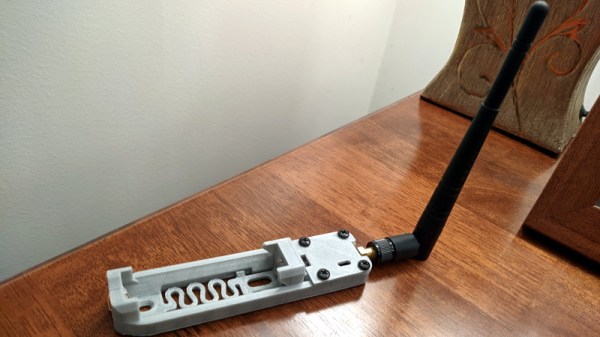
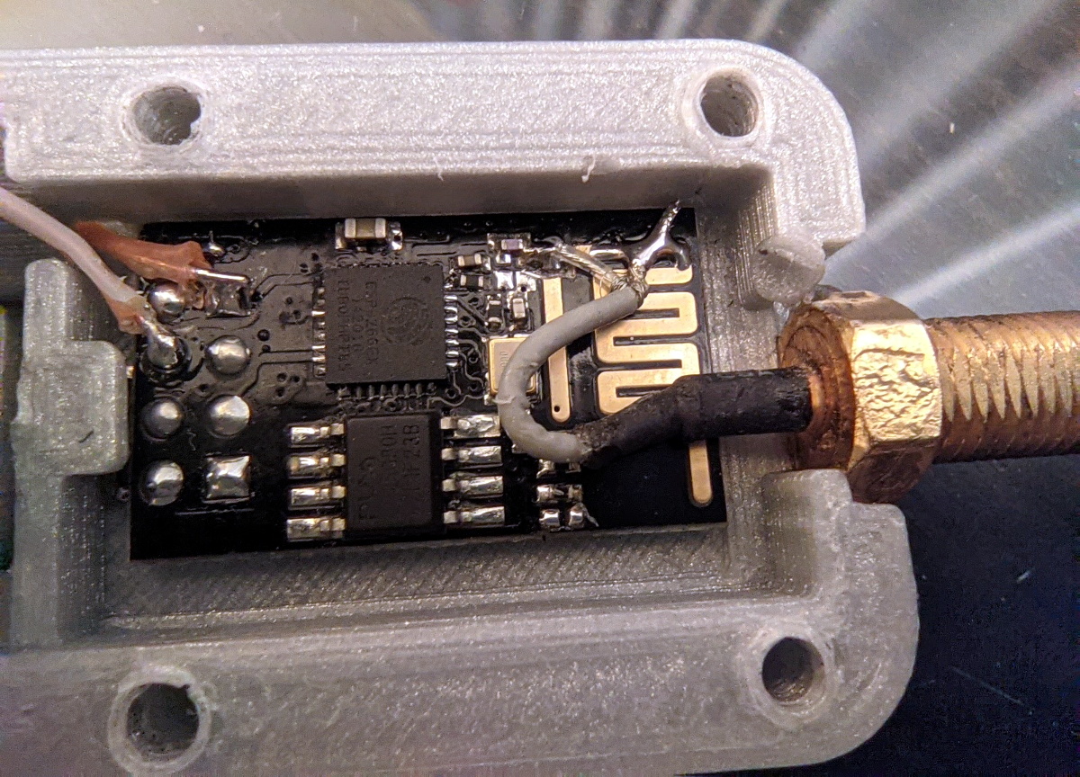 By taking a 3D printed design intended to attach a TP4056 module to the end of an 18650 cell and combining it with an ESP8266 firmware that turns the powerful microcontroller into a WiFi repeater, [bethiboothi] ended up with a portable network node that reportedly lasts up to three days on a charge. The observed range was good even with the built-in PCB antenna, but hacking on an external can get you out a little farther if you need it.
While it doesn’t appear that [bethiboothi] is using it currently, the esp_wifi_repeater firmware does have an automatic mesh mode which seems like it would be a fantastic fit for this design. Putting together an impromptu mesh WiFi network with a bunch of cheap battery powered nodes would be an excellent way to get network connectivity at an outdoor hacker camp, assuming the ESP’s CPU can keep up with the demand.