Cute USART Trick Brings PWM To IR LEDs

We love little tricks like this. Suppose that you want to generate an IR remote’s signal. It’s easy, because most of the codes are known. But it can be slightly harder because most IR remotes and receivers modulate the on pulses with a square wave at roughly 38 kHz for background lighting immunity.

With a competent PWM generator on a microcontroller, you can create this carrier modulation easily enough yourself. Set the PWM frequency to 38 kHz and the duty cycle somewhere in the 33%-50% range, and you’re set. But what if you don’t have a competent PWM generator? Such was the case that prompted [AnalysIR Blog] to fake it, with USART.

Here’s the trick. You set up the serial port to communicate at ten times the desired carrier frequency, and then transmit “special” data. (The number ten comes from eight bits of data plus a start and a stop bit.) If you want a 50% duty cycle, you simply send 0b11110000, as fast as the microcontroller will allow, for a mark and nothing for a space.

There’s some extra detail with inverting the signal if, as most do, your USART idles high. But that’s really it. It’s a cute trick for when you’re desperate enough to need it. And if you’d like to brush up some more on your asynchronous serial skills, check out our guide on troubleshooting USART, and the great comments that ensued.

Hackaday Prize Entry: A Minimal ATtiny Voltage And Frequency Counter

Sometimes when you build something it is because you have set out with a clear idea or specification in mind, but it’s not always that way. Take [kodera2t]’s project, he set out to master the ATtiny series of microcontrollers and started with simple LED flashers, but arrived eventually at something rather useful. An ATtiny10 DVM and DFM all-in-one with an i2c LCD display and a minimum of other components.

The DFM uses the ATtiny’s internal 16 bit timer, which has the convenient property of being able to be driven by an external clock. The frequency to be measured drives the timer, and the time it returns is compared to the system clock. It’s not the finest of frequency counters, depending as it does on the ATtiny’s clock rather than a calibrated crystal reference, but it does the job.

The results are shown in the video below, and all the code has been posted in his GitHub repository. We can see that there is the basis of a handy little instrument in this circuit, though with the price of cheap multimeters being so low even a circuit this minimal would struggle to compete on cost.

Continue reading “Hackaday Prize Entry: A Minimal ATtiny Voltage And Frequency Counter”

Serially, Are You Syncing Or Asyncing?

I know you’ve heard of both synchronous and asynchronous communications. But do you really know the differences between the two?

Serial communication was used long before computers existed. A predecessor is the telegraph system using Morse Code, one of the first digital modes of communication. Another predecessor is the teletype, which set standards that are still used today in your Arduino or Raspberry Pi.

All you need is two wires for serial communications, which makes it simple and relatively robust. One wire is ground and the other the signal. By interrupting the power with predefined patterns, information can be transferred over both short and long distances. The challenge is receiving the patterns correctly and quickly enough to be useful.

I was a bit surprised to find out the serial port on the Arduino Uno’s ATmega328P microcontroller is a Universal Synchronous Asynchronous Transmitter Receiver (USART). I’d assumed it was only a UART (same name, just leave out synchronous) probably because my first work with serial communications was with the venerable Intel 8251 “Programmable Communication Interface”, a UART, and I didn’t expect the microcontroller to be more advanced. Silly me. Later I worked with the Zilog 8530 Serial Controller Chip, a USART, the term I’ll use for both device types.

All these devices function in the same way. You send a byte by loading it into a register and it is shifted out one bit at a time on the transmit (TX) line as pulses. The receiver accepts the pulses on a receive (RX) input and shifts them into a register, which is then read by the system. The transmitter’s job is pretty easy it just shifts out the bits at a known clock rate. The receiver’s task is more complex because it needs to know when to sample the incoming signal. How it does this is the difference between asynchronous and synchronous communications.

Continue reading “Serially, Are You Syncing Or Asyncing?”

AVR Vs PIC, Round 223: Fight!

Get ready to rumble! [Thierry] made the exact same Hello-World-esque project with two microcontrollers (that are now technically produced by the same firm!) to see how the experience went.

It’s not just an LED-blinker, though. He added in a light-detection function so that it only switches on at night. It uses the Forest Mims trick of reverse-biasing the LED and waiting for it to discharge its internal capacitance. The point is, however, that it gives the chip something to do instead of simply sleeping.

Although he’s an AVR user by habit, [Thierry] finds in favor of the PIC because it’s got a lower power draw both when idling and when awake and doing some computation. This is largely because the PIC has an onboard low-power oscillator that lets it limp along at 32 kHz, but also because the chip has a lower power consumption in general. In the end, it’s probably a 10% advantage to the PIC on power.

If you’re competent with one of the two chips, but not the other, his two versions of the same code would be a great way to start familiarizing yourself with the other. We really like his isDarkerThan() function which makes extensive use of sleep modes on both chips during the LED’s discharge period. And honestly, at this level the code for the two is more similar than different.

(Oh, and did you notice [Thierry]’s use of a paper clip as a coin-cell holder? It’s a hack!)

Surprisingly, we’ve managed to avoid taking a stray bullet from the crossfire that occasionally breaks out between the PIC and AVR fans. We have covered a “shootout” before, and PIC won that round too, although it was similarly close. Will the Microchip purchase of Atmel calm the flames? Let’s find out in the comment section. We have our popcorn ready!

What Could Go Wrong: Asynchronous Serial Edition

It’s the easiest thing in the world — simple, straightforward serial data. It’s the fallback communication protocol for nearly every embedded system out there, and so it’s one that you really want to work when the chips are down. And yet! When you need it most, you may discover that even asynchronous serial can cost you a few hours of debugging time and add a few gray hairs to your scalp.

In this article, I’m going to cover most (all?) of the things that can go wrong with asynchronous serial protocols, and how to diagnose and debug this most useful of data transfer methods. The goal is to make you aware enough of what can go wrong that when it does, you’ll troubleshoot it systematically in a few minutes instead of wasting a few hours.

Continue reading “What Could Go Wrong: Asynchronous Serial Edition”

Air Quality Sensors In Every Classroom

One of the first electronics projects for the aspiring hobbyist is wiring a sensor of some sort to a microcontroller, and then doing something useful with the new information. [Brock] has taken this type of gateway project and turned it into a way to get his students involved and familiar with electronics. His take on an air quality meter accomplishes both of these goals, and hopefully helps turn all of his students into the next generation of hackers.

The bill of materials is pretty straightforward. Instead of the go-to Arduino, [Brock] has gone with a Particle Photon which has the added benefits of various wireless connectivity options. The air quality sensor is a Shinyei PP42ns which interfaces easily with the Photon. The only thing that might be out of reach of most public high schools (at least in the United States) is the 3D-printed enclosure, although if you have access to one, [Brock] put the files on the project page so anyone can use them.

Of course, we’re big fans of projects that get students involved in anything beyond standardized tests, and this project goes a long way towards teaching students more than how to pass a test. There are many videos and instructions on the project page if you want to try this on your own, but if the cost for the materials is the only thing scaring you off from doing this in your own classroom there are a few other options. You could use ATtiny chips, or try a different style of sensor, or maybe just try out a different project altogether.

Continue reading “Air Quality Sensors In Every Classroom”

Virtualizing Around The FCC’s Firmware Modification Rules

Last year, the FCC introduced new regulations requiring router manufacturers to implement software security to limit the power output in specific 5GHz bands. Government regulations follow the laws of unintended consequences, and the immediate fear surrounding this new directive from the FCC was that WiFi router manufacturers would make the easiest engineering decision. These fears came true early this year when it was revealed a large router manufacturer was not following the FCC regulations to the letter by limiting the output of the radio module itself, but instead locking down the entire router.

The FCC’s rules regarding the power output of 5GHz routers was never a serious concern; the FCC is, after all, directed to keep the spectrum clean, and can force manufacturers to limit the power output of the wireless devices. The problem comes from how manufacturers implement this regulation – the easiest solution to prevent users from modifying the output of the radio module will always be preventing users from modifying the entire router. Developers don’t like it, the smart users are horrified, and even the FCC is a little flustered with the unintended consequences of its regulation.

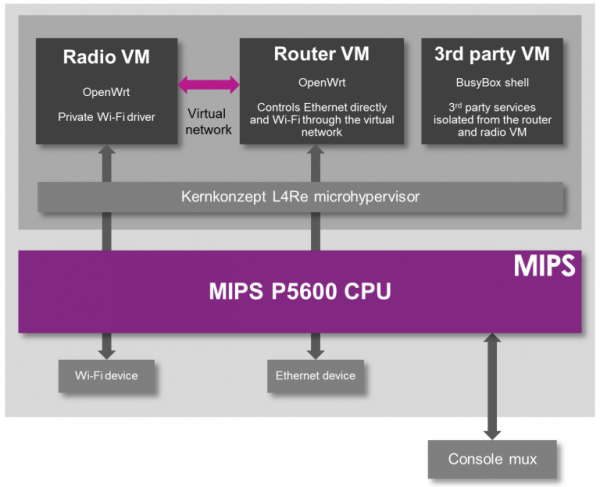
While the easiest solution to preventing the modification of a radio module is to prevent modification to the entire router, there is another way. The folks at Imagination Technologies have come up with a virtualization scheme that allows router manufacturers to lock down the radio module per the FCC directive while still allowing the use of Open Source router firmware like OpenWrt.

A demonstration of the capabilities of this next-generation router comes from the prpl Security Working Group and uses MIPS Warrior CPUs to create multiple trusted environments. The control of the router can be handled by one secure environment, while the rest of the router firmware – OpenWrt included – can be run in an environment more conducive to Open Source firmware.

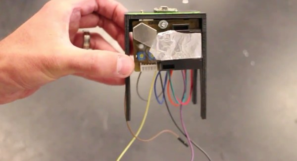
The demo of a compartmentalized, virtualized router uses a dev kit consisting of a dual-core MIPS P5600 CPU running at 1GHz, and a Realtek RTL8192 WiFi adapter plugged into the USB port. The driver for the WiFi adapter runs under a secure hypervisor, making it secure enough to pass the FCC’s muster.

This build wouldn’t be possible without hardware virtualization in microprocessors and microcontrollers. Imagination Technologies has been working on this for a while, and only a few years ago demonstrated a PIC32 with baked in virtualization.

In the video below, Imagination Technologies demonstrates a MIPS board running three virtual machines. The first machine is running OpenWrt, the second is running a WiFi driver, and the third is running third-party applications. Crashing one machine doesn’t bring down the others, and the WiFi driver is locked away in a secure environment in accordance with the FCC regulations.

While it’s hard to imagine a router based on a MIPS board that would be cheaper than the already inexpensive router SoCs found in today’s routers, this method of secure virtualization is the best way to give consumers what they deserve: an open source option for all their devices.

Continue reading “Virtualizing Around The FCC’s Firmware Modification Rules”