Do You Know WHY You’re Supposed To Use Decoupling Capacitors?

[Bertho] really enjoyed pawing through the pile of projects submitted to the 7400 logic contest. But one thing kept hitting him with the vast majority of the entries: decoupling capacitors were missing from the circuits. If you’ve worked with microcontrollers or digital logic chips you probably know that you’re supposed to add a small capacitor in between the voltage and ground pins for decoupling purposes. But do you know why? [Bertho] put together a great post that looks that the benefits of using decoupling capacitors in your circuits.

He set up a circuit using a 74HC04 inverter and put it to the test. The image above shows current measurments with the inverter under load. Images on the right show a decoupled circuit and the ones on the left shows a circuit without that capacitor. You can see that the decoupled circuit has much smoother signals when driven high. But it’s not just the smoothness that counts here. [Bertho] goes on to discuss the problem of slow rise-time caused by a dip in current flowing into a chip’s VCC pin. It can take a long time to get above the threshold where a chip would recognize a digital 1. Throwing a capacitor in there adds a little reservoir of current, just waiting to fill in when the power rail dips. This feeds the chip in times of need, keeping those logic transitions nice and snappy.

Wicked Use Of HTML5 To Display Sensor Data

This project shows you one possible way to use HTML5 to fully integrate sensor data from a microcontroller into our technological lives. Now, when we saw this tip come through our inbox we thought it would be an interesting example to learn from but we weren’t ready for how truly cool the setup is. Take a look at the video after the break and you’ll see that scanning the QR code on the project box will immediately start a 10ms resolution live stream of the accelerometer data. Furthermore, the browser page that the phone loads allows you to send what you’re currently viewing to the main frame of a browser running on a different computer with the touch of a button. In this way you can build a dashboard of streaming sensor data. Talk about the future of home automation. Imagine a QR code on your thermostat that allows you gain access to your home’s heating, air conditioning, humidifier, and water heater performance and controls just by snapping a pic? The sky’s the limit on this one so let us know what you’d use it for by leaving a comment.

In this case an mbed microcontroller is handling the data acquisition and pushing that to a server via a WiFly module using the WebSockets library. This data is pushed in the form of a JSON packet which is distributed by the server as a data stream. Clients can access it via a browser through a page that makes use of JavaScript.

Continue reading “Wicked Use Of HTML5 To Display Sensor Data”

Snooping Around In The Iclicker Hardware And Firmware

[Arko] was compelled to purchase an iclicker to use in some of his college courses. It’s similar in size to a television remote control except it only has six buttons and it communicates via radio frequency instead of infrared light. The idea is that classrooms have a base station that the instructor uses, and he or she can ask questions of the class and have instant feedback. Results are often projected on a screen for all to see but only the instructor can get at the breakdown of who answered in what way. In [Arko’s] case, the class awards participation points that you can only get by using this device. He decided to actually learn something from the expenditure by reverse engineering the device.

Preliminary hardware inspection told him that it uses an ATmega8 microcontroller and there’s a standard 6-pin ISP footprint just waiting to be populated with a surface mount pin header. Once he soldered on that header, he tried to read out the firmware but the iClicker reset itself. He guessed that there was something going on with the power and ground lines so he soldered directly to them and was able to dump the data–the security fuses are not set. He goes on to snoop in the EEPROM to find where the device ID is stored, and then to watch some of the SPI communications to see what the microcontroller is sending to the radio chip. But there’s a lot left to discover and he’s planning at least two follow-up post to share what he finds.

Just looking to repair your dead device? Check out this tip on battery problems with the iclicker.

Building Optical Flex Sensors

[Joel] dug up this hack that he pulled off over ten years ago. It’s inspired by the Nintendo PowerGlove, and uses flex sensors to react to movements of your fingers. The interesting thing is, he built these optical flex sensors himself.

He likes to say that this is a ghetto fiber-optic setup. The inlaid diagram above gives you an idea of how the sensors work. An IR LED and infrared diode are positioned at either end of a piece of clear aquarium tubing. When the tube is flexed, the amount of light that makes it to the diode is diminished, a change that can be measured by a microcontroller. [Joel] found that he could increase the resolution of the sensor by adding something to the center of the tube, blocking the light when not straight. In this case he used pieces of scrap wire. The outside of the sensor was also wrapped in shrink tubing to keep ambient light from interfering with measurements.

He uses a trimpot to tune the sensors but we wonder how hard it would be to add a calibration algorithm to the firmware?

C64 Joystick Adapter

[Marcus Gritsch] wanted to do his retro gaming using retro hardware… or at least using some retro hardware. Although he was playing his Commodore 64 games in an emulator, he figured that using an original controller would boost the nostalgia quite a bit. This is a vintage Competition Pro joystick that has buttons and a joystick of a similar quality to arcade hardware and a DE-9 connector. He managed to connect new to old by building his own USB to C64 joystick adapter.

His project started out by breadboarding a circuit based on a PIC 24FJ64GB002 microcontroller. This does all of the work, having native USB support, and no problem reading and translating the signals from the old hardware which are simply conductors for each internal switch that pull to ground when actuated. Once working, he soldered everything to some protoboard; a connector at each end, the chip itself, a voltage regulator, and some passive components. It’s a, robust build that should give him years of emulated fun.

Throw Together A Temperature Logger In Minutes

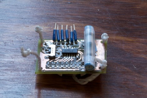
[Rajendra] found an easy way to make a USB temperature logger. He already had a USB to UART adapter that takes care of the heavy lifting. On one end it’s got the USB plug, on the other a set of pins provide a ground connection, 3.3V and 5V feed, as well as RX/TX lines.

To get the hardware up and running all he needed was something to read a temperature sensor and push that data over the serial connection. An 8-pin microcontroller in the form of a PIC 12F1822 does the trick. It runs off of the 5V pin on the USB-UART, and uses the ADC to get temperature data from an MCP9701A sensor.

The sample rate is hard-coded into to the PIC’s firmware, but adding a button, or coding some serial monitoring could easily make that configurable. [Rajendra] used Processing to write an app which displays the incoming temperature info and uses the computer to time-stamp and log the inputs. We could see this as a quick solution to tracking wort temperature during fermentation to make sure your beer comes out just right.

How To Develop For STM32 Discovery Boards Using Linux

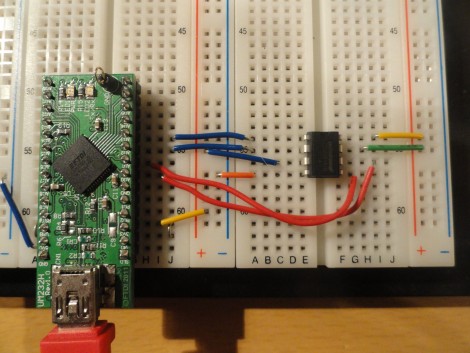
Some hard work has gone into making it possible to develop for the STM32 Discovery board using a Linux system. The board boasts an ARM Cortex-M3 processor, which can be programmed via the mini-USB port on the side. But the company only supports development through their IDE’s which don’t run natively on Linux. The stlink project aims to solve this, providing a toolchain, and making it possible to flash the microcontroller via the USB connection.

The github project linked above also includes a tutorial to get you started (pdf). In addition to a walk through on compiling the software packages, it includes a simple blink program that you can use to test out your hardware. GDB, the familiar open-source debugger, is used to flash the chip. This is a bare-bones tutorial so if you end up posting about your experiences using this toolchain with the Discovery boards we’d love to hear about it.

[Thanks Texane]