These days, Internet connectivity is ubiquitous, so you can look up live weather data on just about any device around you. Regardless, [Jozerworx] wanted a simple, clean, independent weather display, and came up with this simple design.
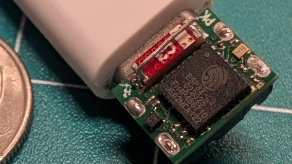
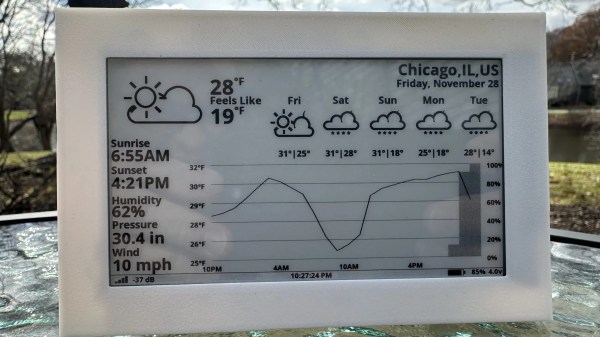
The build is based on the Lilygo T5 EPD devboard, which combines an ESP32-S3 microcontroller with a nice 4.7-inch e-paper display. This display has the benefit that it only uses power when it’s being updated, making it particularly suitable to run off a battery for extended periods of time. Meanwhile, the ESP32 and its inbuilt Wi-Fi connectivity allow it to query the internet for updated weather forecasts. Weather data is sourced via the OpenWeather API, which [Jozerworx] notes comes with the caveat of requiring an API key. It’s a little fussy, but if you want good weather data, there are few easier ways to get it. The display shows a forecast for the next five days, while also showing graphs of ambient temperature and humidity along with useful information like the sunset and sunrise schedule.
Files are on Github for those eager to learn more. [Jozerworx] also notes that getting started with the display is particularly easy with the inclusion of a setup mode. This allows the display to act as a Wi-Fi access point with a web page that you use enter your home Wi-Fi connection details.
We’ve featured a great many charming weather displays over the years, too. If you’re working to plot, chart, or even predict the weather—don’t hesitate to show us your cool projects over on the tipsline!
Continue reading “Build Yourself A Graphing Weather Display”

![[Piers] explains his code](https://hackaday.com/wp-content/uploads/2025/11/One-ROM-PIO-banner.jpg?w=600&h=450)