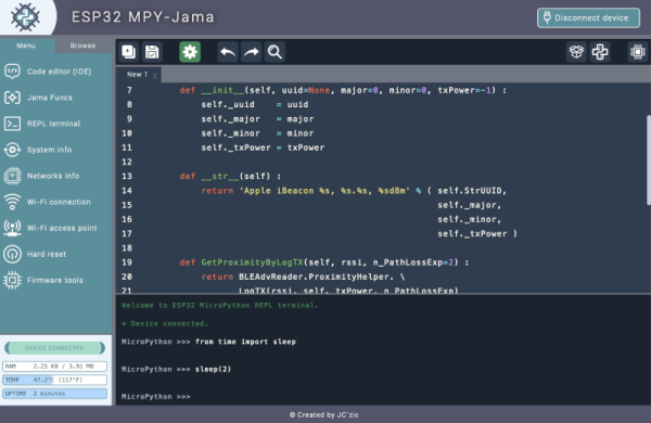
In theory, using MicroPython on the ESP32 is easy — just flash an image and connect using a serial port. But that leaves a lot of things you still have to do. You need to move files between the two platforms. You’ll want to manage network configurations. You might want better editing and assistance, too. So there are a number of IDEs made to help you and one we recently noticed was MPY-Jama.
The IDE provides source code editing, of course. But it also allows you to do things like pull information about the network using a dashboard or connect to a WiFi network easily. You can even create your own AP with a simple interface.
Although the front part of the README mentions it is for Windows or Mac, if you scroll down you’ll find instructions for installing under Linux. The IDE is extensible using “Jama Funcs” and can handle the flashing operation from inside the IDE.
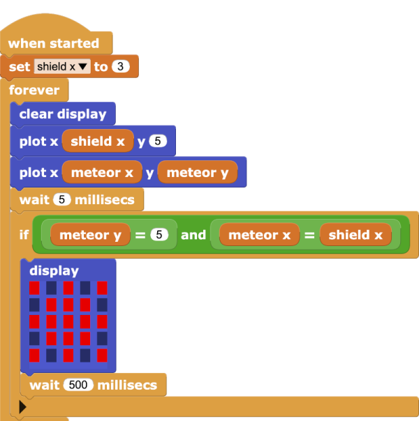
Of course, there is an IDE from Arduino (but not the Arduino IDE) that handles MicroPython. You can also find a rundown of several similar alternatives online. If you need some inspiration for a MicroPython project, perhaps you’d like to play a game?