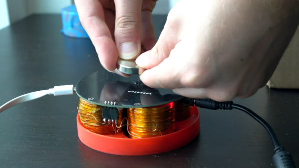
We are big fans of the little desktop magnetic levitation setups that float a small object on a magnet. As [3D Printed Life] points out, they look like magic. He was surprised that the commercial units use analog electronics. He decided to build a digital version but didn’t know what he was getting into. He details his journey in the video you can see below.
Along with a custom control board, he decided to wind his own electromagnets. After finding that tedious he built a simple coil winder to automate some of the work.
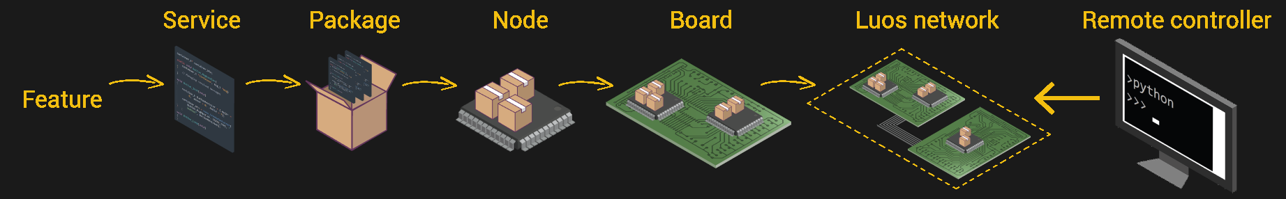
Those of us tasked with developing firmware for embedded systems have a quite a few hurdles to jump through compared to those writing for the desktop or mobile platforms. Solved problems such as code reuse or portability are simply harder. It was with considerable interest that we learnt of another approach to hardware abstraction, called Luos, which describes itself as micro-services for embedded systems.
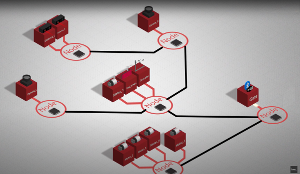
This open source project enables deployment of distributed architectures composed of collaborating micro-services. By containerizing applications and hardware drivers, interfaces to the various components are hidden behind a consistent API. It doesn’t even matter where a resource is located, multiple services may be running on the same microcontroller, or separate ones, yet they can communicate in the same way.
By following hardware and software design rules, it’s possible to create an architecture of cooperating computing units, that’s completely agnostic of the actual hardware. Microcontrollers talk at the hardware level with a pair of bidirectional signals, so the hardware cost is very low. It even integrates with ROS, so making robots is even easier.
Luos architecture
By integrating a special block referred to as a Gate, it is possible to connect to the architecture in real-time from a host computer via USB, WiFi, or serial port, and stream data out, feed data in, or deploy new software. The host software stack is based around Python, running under Jupyter Notebook, which we absolutely love.
Current compatibility is with many STM32 and ATSAM21 micros, so chances are good you can use it with whatever you have lying around, but more platforms are promised for the future.
Now yes, we’re aware of CMSIS, and the idea of Hardware Abstraction Layers (HALs) used as part of the platform-specific software kits, this is nothing new. But, different platforms work quite differently, and porting code from one to another, just because you can no longer get your preferred microcontroller any more, is a real drag we could all do without, so why not go clone the GitHub and have a look for yourselves?
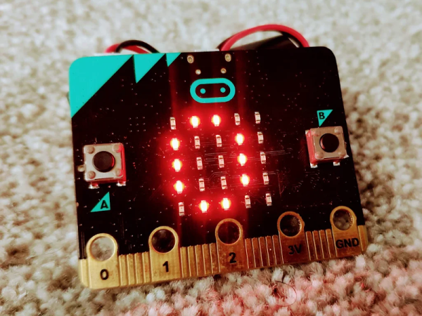
We always have mixed feelings about the drag-and-drop programming languages. But we were impressed with [SirDan’s] Morse code decoder built with the graphical MakeCode. Granted, it is reading 5 element groups from a button on the BBC micro:bit and not worrying about details such as intercharacter or interelement spacing or word spacing. But it is still a nice demo for MakeCode.
Interestingly, the online editor for MakeCode can apparently simulate well enough to test the program. However, [SirDan] only provides the hex file so we couldn’t try it out. There is a screenshot of the visual code, but you’d have to work out the part that didn’t fit on the screenshot (the data arrays are pretty long).
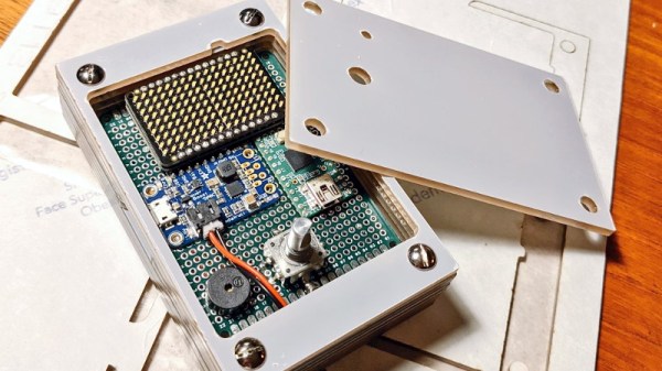
Looking for something with a bit more style than the traditional kitchen timer, [Martin Jonasson] decided to take the last couple of months to design and build his own take on the idea using a rotary encoder, 16×9 LED matrix, and a Teensy 2.0 microcontroller. Were there better things he could have spent that time on? Possibly. But you probably wouldn’t have been reading it about it here, so we won’t trouble ourselves with such thoughts.
Put together on a piece of perfboard, the handwired circuit also includes an Adafruit PowerBoost 500 Charger, a 3.7 V 2500 mAh LiPo battery, a IS31FL3731 Charlieplexed PWM LED driver, and a piezo buzzer. The top of the rotary encoder has been capped off with a sold metal knob, which combined with the enclosure made of stacked laser cut 3 mm acrylic sheets, really gives the device a very sleek and classy look.
While the hardware is quite nice, it’s the software that really pulls this whole project together. A game developer by trade, [Martin] went all in on the timer’s GPLv3 licensed firmware. From using the toneAC library to play melodies at the end of the countdown, to the custom fonts and the code that pauses the timer while the user is spinning the knob, there’s plenty of little touches that should make the timer a joy to use. We’ve seen some unique kitchen timers over the years, but the attention to detail put into this build really raises the bar.
[Martin] has provided everything you need to create your own version of his timer, including the SVG file for the laser cut case. While not strictly required, coming up with a custom PCB for this project would be a nice touch, should you want to put your own spin on it.
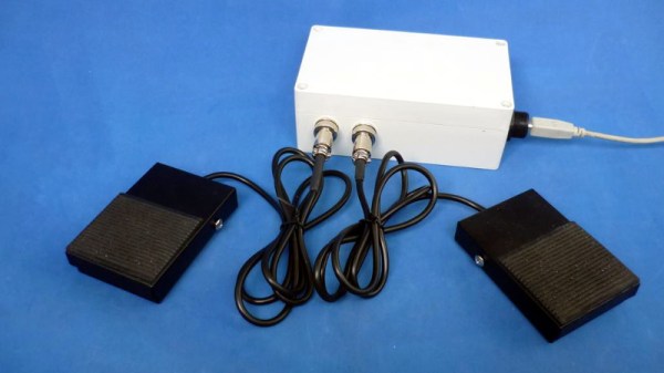
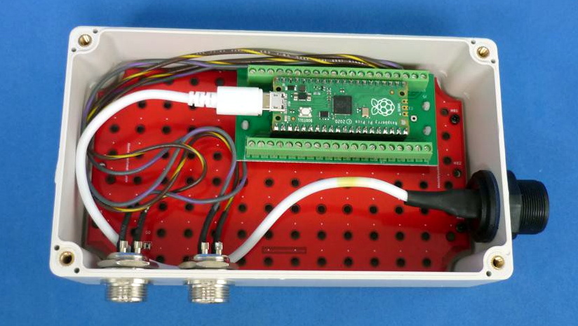
With its copious number of GPIO pins and native USB, the Raspberry Pi Pico is arguably the ideal microcontroller for developing your own platform agnostic USB Human Input Devices. But you don’t have to take our word for it. Check out how quickly the $4 USD board allowed [Alberto Nunez] to put together a pair of foot pedals for his computer.
Wiring doesn’t get much easier than this.
A peek inside the enclosure reveals…well, not a whole lot. All that’s hiding inside that heavy-duty plastic box is the Pi Pico and some screw down terminals that let [Alberto] easily wire up the female bulkhead connectors for the pedals themselves. Incidentally, while you could certainly make your own pedals, the ones used for this project appear to be the sort of commercially available units we’ve seen used in similar projects.
With the hardware sorted, [Alberto] just needed to write the software. While he could have taken the easy way out and hard coded everything, we appreciate that his CircuitPython script loads its configuration from a text file. This allows you to easily configure which GPIO pins are hooked up to buttons, and what key codes to associate them with. He didn’t really need to go through this much effort for his own purposes, but it makes the project far easier to adapt for others, so our hats off to him.
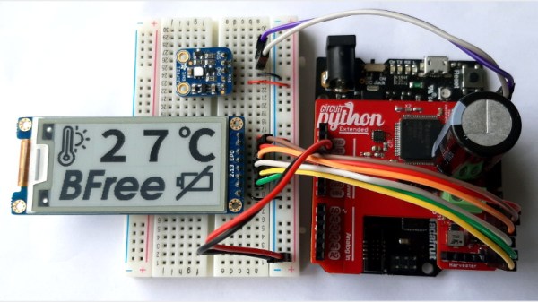
Generally speaking, we like our computing devices to remain on and active the whole time we’re using them. But there are situations, such as off-grid devices that run on small solar cells, where constant power is by no means a guarantee. That’s where the concept of intermittent computing comes into play, and now thanks to the BFree project, you can develop Python software that persists even when the hardware goes black.
Implemented as a shield that attaches to a Adafruit Metro M0 Express running a modified CircuitPython interpreter, BFree automatically makes “checkpoints” as the user’s code is running so that if the power is unexpectedly cut, it can return the environment to a known-good state instantaneously. The snapshot of the system, including everything from the variables stored in memory to the state of each individual peripheral, is stored on the non-volatile FRAM of the MSP430 microcontroller on the BFree board; meaning even if the power doesn’t come back on for weeks or months, the software will be ready to leap back into action.
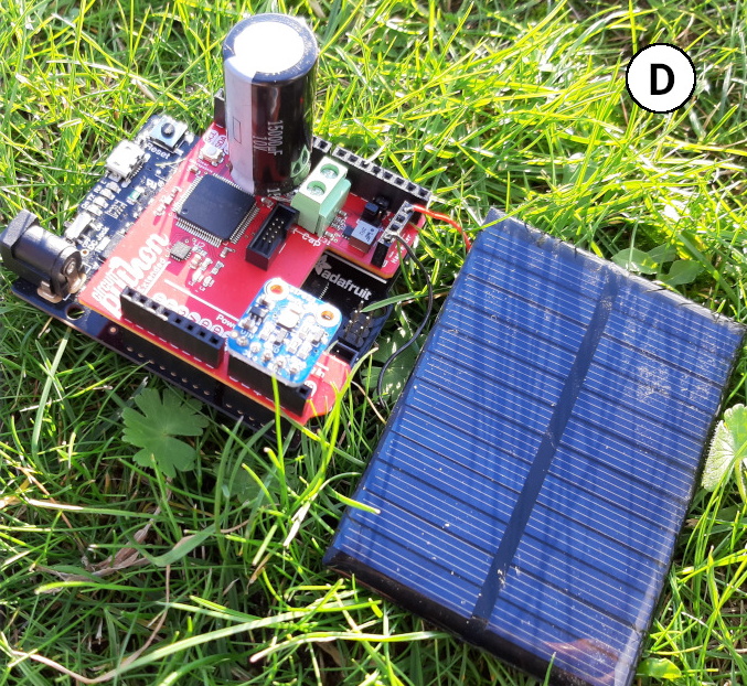
In addition to the storage for system checkpoints, the BFree board also includes energy harvesting circuity and connections for a solar panel and large capacitor. Notably, the system has no provision for a traditional battery. You can keep the Metro M0 Express plugged in while developing your code, but once you’re ready to test in the field, the shield is in charge of powering up the system whenever it’s built up enough of a charge.
The product of a collaboration between teams at Northwestern University and Delft University of Technology, BFree is actually an evolution of the battery-free handheld game they developed around this time last year. While that project was used to raise awareness of how intermittent computing works, BFree is clearly a more flexible platform, and is better suited for wider experimentation.
We’ve seen a fair number of devices that store up small amounts of energy over the long term for quick bouts of activity, so we’re very interested to see what the community can come up with when that sort of hardware is combined with software that can be paused until its needed.
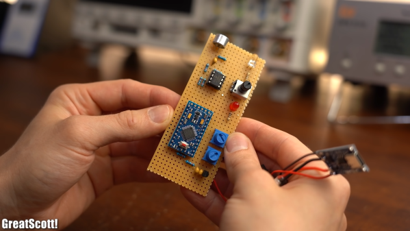
Everyone loves watching movies, that is, so long as you can hear what the characters on screen are saying. [GreatScott] found this second part difficult while watching through BladeRunner 2049, so he designed an automatic volume adjuster to assist.
At a high level, the solution is fairly straightforward; when there is loud music playing in a movie, turn the volume down. The challenge is how to actually achieve that. The first step was controlling the volume. To avoid having to modify or damage his sound system, [GreatScott] opted instead to mimic the volume up and down signals of his remote over IR. Using the very handy IRremote library for Arduino and its built-in decoding functionality, he was able to identify and replicate the signals with his own IR LED.
The second step in this process was measuring the volume of the movie. [GreatScott] achieved this with a microphone and amplifier circuit, that was then piped into one of the analog pins of the Arduino Pro Micro at the heart of the build. Since the audio being sampled could have a frequency as high as 20 kHz, the ADC Prescaler had to be adjusted from its standard value, which would have only permitted measurements at less than 5 kHz.
The third step was writing the algorithm to detect loud music and adjust the volume accordingly. The Arduino will measure the audio until a sound greater than the dead band value, set with one of the two onboard potentiometers, is detected. This then triggers the Arduino to start a timer, to see how frequently the upper limit is being surpassed. If it is just one or two occasionally loud noises (like a scream, a clap, whistling, etc.) the Arduino will not take any action, but multiple loud noises in rapid succession will then trigger the volume down command over the IR LED. A second potentiometer allows for adjustment of this timer’s critical value, so that you can make the system respond faster or slower depending on the movie.
Once the sound has been detected to have dropped down below a critical vaue, the Arduino assumes that the movie is back to dialog and will increase the volume by the number of times it decreased it before, leaving you back at the perfect volume.
Maybe you’re the type that cares more for the visuals of a movie, rather than the audio. In that case, this e-paper movie display will be perfect for giving you time to appreciate every frame!