For one-off projects or prototyping, it’s not too hard to find a wall wart or power supply to send a few joules of energy from the wall outlet to your circuit. Most of these power supplies use a transformer to step down the voltage to a more usable level and also to provide some galvanic isolation to the low voltage circuit. But for circuits where weight, volume, or cost are a major concern, a transformer may be omitted in the circuit design in favor of some sort of transformerless power supply.
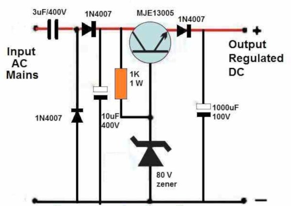
While power supplies with this design do have many advantages, some care needs to be taken with regard to safety. The guide outlines four designs of increasing complexity which first puts out a basic transformerless power supply, using a series capacitor to limit current. To bring the voltage to an acceptable level, a recognizable bridge rectifier is paired with a capacitor as well as a zener diode. The second circuit presented adds voltage stabilization using a transistor and 78XX regulator. From there, zero-crossing detection is added to limit inrush surge currents, and the final design uses the venerable 555 timer to build a switching power supply.
Although it is noted several times throughout the guide, we’ll still point out here that transformerless designs like these introduce several safety issues since a mistake or fault can lead to the circuit being exposed to the mains voltage. However, with proper care and design it’s possible to make use of these designs to build more effective power supplies that can be safe to use for powering whatever circuit might energy but might not require the cost or weight of a transformer. For more on the theory of these interesting circuits and a few examples of where they are often found, check out the shocking truth about transformerless power supplies.
Thanks to [Stephen] for the tip!