On no planet is making your own X-ray tube a good idea. But that doesn’t mean we’re not going to talk about it, because it’s pretty darn cool.
And when we say making an X-ray tube, we mean it — [atominik] worked from raw materials, like glass test tubes, tungsten welding electrodes, and bits of scrap metal, to make this dangerously delightful tube. His tool setup was minimalistic as well– where we might expect to see a glassblower’s lathe like the ones used by [Dalibor Farny] to make his custom Nixie tubes, [atominik] only had a small oxy-propane hand torch to work with. The only other specialized tools, besides the obvious vacuum pump, was a homebrew spot welder, which was used to bond metal components to the tungsten wires used for the glass-to-metal seals.
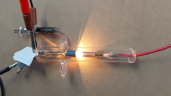
Although [atominik] made several versions, the best tube is a hot cathode design, with a thoriated tungsten cathode inside a copper focusing cup. Across from that is the anode, a copper slug target with an angled face to direct the X-rays perpendicular to the long axis of the tube. He also included a titanium electrode to create a getter to scavenge oxygen and nitrogen and improve the vacuum inside the tube. All in all, it looks pretty similar to a commercial dental X-ray tube.
The demonstration in the video below is both convincing and terrifying. He doesn’t mention the voltage he’s using across the anode, but from the cracking sound we’d guess somewhere around 25- to 30 kilovolts. The tube really gets his Geiger counter clicking.
Here’s hoping [atominik] is taking the proper precautions during these experiments, and that you do too if you decide to replicate this. You’ll also probably want to check out our look at the engineering inside commercial medical X-ray tubes.
Continue reading “This Scratch-Built X-Ray Tube Really Shines”