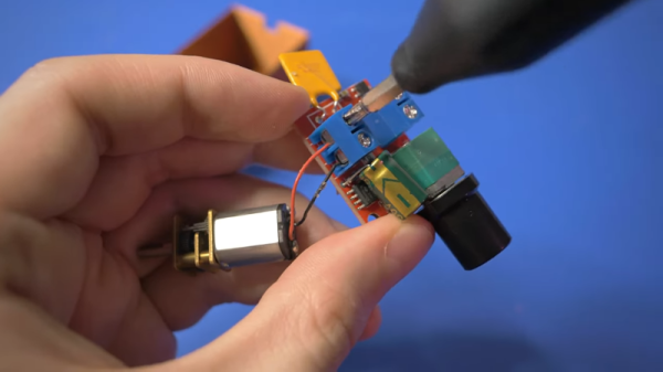
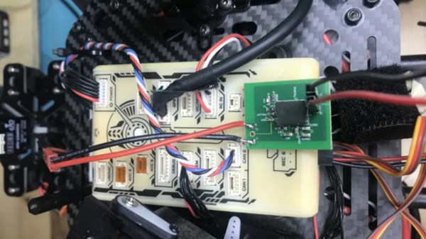
Once you get tired of printing keychains and earbud holders with your 3D printer, you’ll want to design things a bit more sophisticated. How about things that rotate? [3DSage] has a good how-to about how to integrate a simple motor and controller into a few different size boxes. Combined with some 3D printed linkages, these boxes can turn your project — printed or otherwise — into something that spins.
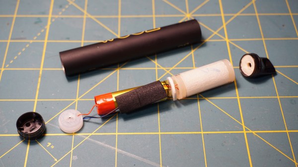
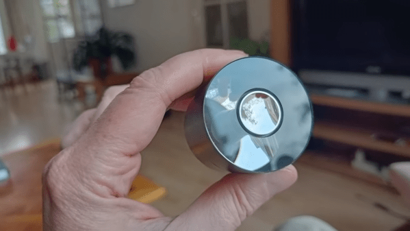
To demonstrate, he created a few cat toys, played with an idea for a magic trick, and refit a selfie light into… something. We have no doubt you can find something to do with these little motor modules. The boxes vary mostly in how big the battery packs are. There are also several interesting side pieces like a 3D holder for rechargeable button cells and their charger.
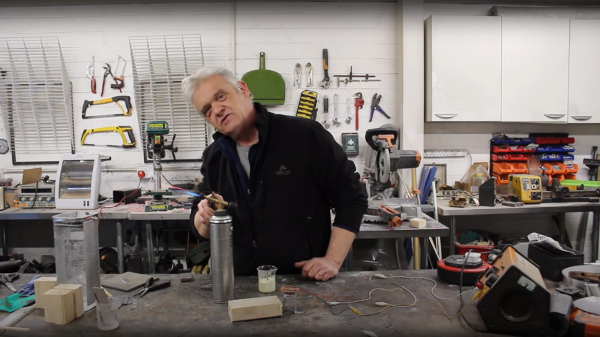
In addition, he also demonstrates how to use the motor as a (rather poor) generator. Attaching a water wheel wasn’t a success until he used compressed air to run the wheel. You would have thought water would have done the trick.
The video stresses that you should solder connections, but you don’t have to. Honestly, we think if you are building moving stuff with a 3D printer, you should probably just go ahead and learn to solder. It isn’t that hard and there are plenty of reasons to learn.
Of course, you could 3D print the motor itself. Adapting motor modules for different uses isn’t a new idea, of course, but it is always great to see more ways to apply basic components.
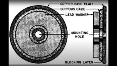 based not upon silicon or germanium, but copper. Copper (I) Oxide is a naturally occurring P-type semiconductor, which can be easily constructed by heating a copper sheet in a flame, and scraping off the outer layer of Copper (II) Oxide leaving the active layer below. Simply making contact to a piece of steel is sufficient to complete the device.
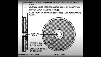 as the Selenium rectifier, based on the properties of a Cadmium Selenide – Selenium interface, which forms an NP junction, albeit one that can’t handle as much power as good old copper. One final device, which was a bit of an improvement upon the original CuO rectifiers, was based upon a stack of Copper Sulphide/Magnesium metal plates, but they came along too late. Once we discovered the wonders of germanium and silicon, it was consigned to the history books before it really saw wide adoption.


