Regardless of how you might feel about Apple and the ecosystem they’ve cultured over the years, you’ve got to give them some credit in the hardware department. Their “Retina” displays are a perfect example; when they brought the 2,048 by 1,536 panel to the iPad 3, the technology instantly became the envy of every tablet owner. But what if you want to use one of these gorgeous screens outside of Apple’s walled garden?
 As it turns out, there are a number of options out there to use these screens on other devices, but [Arthur Jordan] wasn’t quite happy with any of them. So he did what any self respecting hacker would do, and built his own adapter for iPad 3 and 4 screens. Not that he did it completely in the dark; his design is based on the open source Adafruit Qualia driver, which in turn was based on research done by [Mike’s Mods]. A perfect example of the open source community at work.
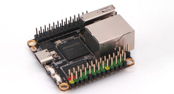
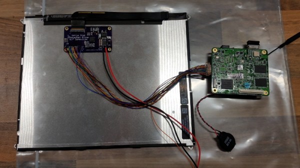
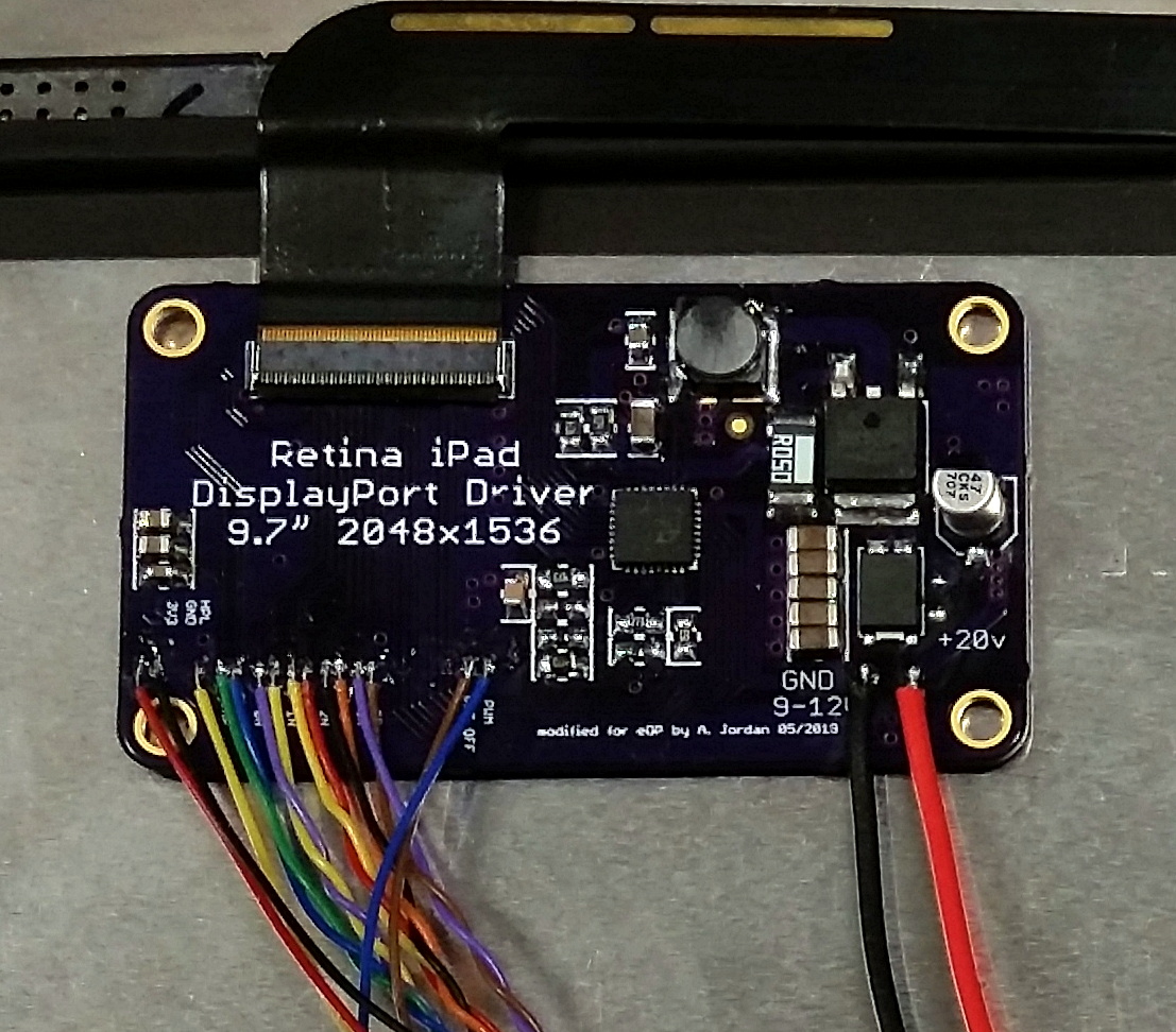
The resulting board allows you to connect the Retina display from the iPad 3 or 4 to any device that features Embedded DisplayPort (eDP). Rather than put a dedicated port on his board, [Arthur] just left bare pads where you can solder up whatever interface method your particular gadget might use. In his case, he wanted to hook it up to an x86 UP Core SBC, so he even came up with a seperate adapter that breaks out that board’s diminutive display connector to something that can be soldered by hand.
So what’s different between the board [Arthur] developed and Adafruit’s Qualia? Primarily its been made smaller by deleting the DisplayPort connectors in favor of those bare pads, but he’s also dumped the backlight control hardware and 3.3V regulator that in his experience hasn’t been necessary with the eDP devices he’s worked with. So if space is a concern in your build, this version might be what you’re after.
We’ve seen other Retina display adapters in the past, and of course the iPad isn’t the only high-end device that’s had a screen good enough to reuse on its own. The lesson here is that if you put a must-have feature in your product, don’t be surprised when some hacker comes along and figures out how to liberate it for their own purposes.