Ask Hackaday: Is There A Common Mechanical Parts Library?

Like many stories, this one started on the roof. This particular roof is located in Michigan and keeps the rain and snow off of the i3Detroit hackerspace. Being an old industrial building, things up on the roof can start getting creaky, and when an almighty screech started coming from one of the rooftop vents as it swiveled in the wind, Nate, one of the group’s coordinators, knew it was time to do something about it.

Previous attempts to silence the banshee with the usual libations had failed, so Nate climbed up to effect a proper repair with real bearings. He dug into the unit, measured for the bearing, and came down to order the correct items. That’s when it struck him: How many should I order? After all, bearings are useful devices, not just to repair a wonky vent but especially handy in a hackerspace, where they can be put to all sorts of uses. Would extra bearings be put to good use, or would they just sit on a shelf gathering dust?

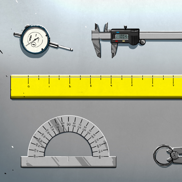
That’s when Nate dropped us a line and asked a question that raises some interesting possibilities, and one which we couldn’t answer offhand: Is there a readily accessible online library of common mechanical parts?

Continue reading “Ask Hackaday: Is There A Common Mechanical Parts Library?”

Memristors On A Chip Solve Partial Differential Equations

We were always taught that the fundamental passive components were resistors, capacitors, and inductors. But in 1971, [Leon Chua] introduced the idea of a memristor — a sort of resistor with memory. HP created one in 2008 and since then we haven’t really had the burning need to use one. In a recent Nature article, [Mohammed Zidan] and others discuss a 32 by 32 memristor array on a chip they call a memory processing unit. This analog computer on a chip is useful for certain kinds of operations that CPUs are historically not efficient at, including solving differential equations. Other applications include matrix operations used in things like machine learning and weather prediction. The paper is behind a paywall, although the usual places to find scholarly papers will probably have it soon.

There are several key ideas for using these analog elements for high-precision computing. First, the array is set up in a passive crossbar arrangement. In addition, the memristors are quantized so that different resistance values represent different numbers. For example, a memristor element that could have 16 different resistance values would allow it to operate as a base-16 digit.

Continue reading “Memristors On A Chip Solve Partial Differential Equations”

Monoprice Mini Converted To Pick And Place (Kinda)

Would you believe that you can take a cheap 3D printer and easily convert it into a full function pick and place machine to help assemble your PCBs? No? Well good, because you can’t. A real pick and place needs all kinds of sensors and logic to identify parts, rotate them, make sure everything is aligned, etc, etc. There’s no way you could just bolt all that onto a cheap 3D printer, and let’s not even talk about the lack of closed loop control.

But if you have a very specific use case, namely a PCB that only has a relatively large single part that doesn’t need to be rotated, [Connor Nishijima] might have a solution for you. He bought a $150 USD Monoprice Mini, and with the addition of a few printed parts, was able to build a machine that drastically cuts down the time it takes for him to build his LED boards. Best of all the modification doesn’t involve any permanent changes to the printer, he can just pop off the vacuum attachment when he wants to print something.

Beyond the 3D printed parts (which were made on the printer itself), the only thing you need to make the modification is the vacuum pump. [Connor] is using a hot air station that includes a vacuum pump for picking up SMD components, but he mentions that you’d probably better off just modifying an aquarium pump and using that. A printed holder snaps over the cooling fan of the Monoprice Mini to hold the vacuum pickup tool, and another printed piece holds the strip of LEDs and the PCB. It’s worth noting that the machine has no ability to control the vacuum pump, and doesn’t need to. The pickup tool is so weak that when the LED lands in the solder paste it sticks to the board well enough that the tool can’t lift it back off.

The real genius in this build comes from the manually written G-Code. You load it from the printer’s built in menu system as if it was a normal 3D print, and it instructs the printer to move the vacuum tool over the line of LEDs, pick one up, and drop it in place on the PCB. It then uses a small peg built into the vacuum tool holder to advance the line of LEDs before starting the cycle all over again. Incredibly, it does this whole complex dance 20 times for each PCB without ever having any kind of feedback or alignment check. It only works because [Connor] was willing to go through the trial and error of getting the calibration and G-Code down as close to perfect as can be expected for such a cheap machine.

This isn’t the first time we’ve seen the Monoprice Mini converted into something a bit more impressive than a cheapo 3D printer. Seems that for whatever the machine lacks in the printing department, it more than makes up for in hackability.

Continue reading “Monoprice Mini Converted To Pick And Place (Kinda)”

The PT2399 Delay/Echo Chip Data Sheet You Never Had

If you are fortunate enough to have had the opportunity to play with an analogue-reel-to-reel tape recorder in a well-equipped studio, you probably looped the tape around to create an echo, or a delay in the audio. It was a desirable effect to have, but not a practical one for a guitar pedal or similar portable accessory. Silicon alternatives for creating delays have been in production since the 1960s, first the so-called bucket brigade delay lines that used a switched chain of on-chip capacitors, and more recently all-digital chips that process the delay by storing samples in RAM. One of the more popular of those is the Princeton Technology PT2399, but it comes with something of a snag for the experimenter in the form of a sparse data sheet. Thankfully the folks at [Electrosmash] have come to the rescue on that front with a thorough technical examination of the chip that should fill in any gaps in the official documentation.

After a brief examination of the range of chips of which the 2399 is a part, they dive right into the chip’s internals by rearranging the internal circuit diagram from the data sheet to the point at which it makes more sense. At which point the difference between the chip’s delay and echo functions becomes obvious, through the inclusion of a feedback path.

We then are taken through the pins, examining what lies behind the power supply and analog inputs and outputs. We are somewhere between a data sheet and an app note here, as some of this is information rarely present even in really good data sheets. Finally, we are taken through the chip’s performance, with real-world distortion and noise measurements. Armed with this page, the would-be PT2399 designer really can say they know what they are working with.

Surprisingly few PT2399s have appeared on these pages, however one did pop up in the Synthbike.

TL084 die blocks

Ken Shirriff Found Butterflies In His Op-Amp

In 1976, Texas Instruments came out with the TL084, a four JFET op-amp IC each with similar circuitry to Fairchild’s very popular single op-amp 741. But even though the 741 has been covered in detailed, when [Ken Shirriff] focused his microscope on a TL084, he found some very interesting things.

JFETs on the TL084 op-amp

To avoid using acid to get at the die, he instead found a ceramic packaged TL084 and pried off the cover. The first things he saw were four stabilizing capacitors, by far the largest structures on the die and visible to the naked eye.

When he peered into his microscope he next saw butterfly shapes which turned out to be pairs of input JFETs. The wide strips are the gates and the narrower strip surrounded by each gate is the source. The drain is the narrow strip surrounding each gate. Why arrange four JFETs like this? It’s possible to have temperature gradients in the IC, one side being hotter than the other. These gradients can affect the JFET’s characteristics, unbalancing the inputs. Look closely at the way the JFETs are connected and you’ll see that the top-left one is connected to the bottom-right one, and similarly for the other two. This diagonal cross-connecting cancels out any negative effects.

[Ken’s] analysis in his article doesn’t stop there though. Not only does he talk more about these JFETs but he goes over the rest of the die too. It’s well worth the read, as is his write-up about the 741 which we’ve also covered.

Dissecting The Elusive Wax Motor

We’d wager most readers aren’t intimately acquainted with wax motors. In fact, a good deal of you have probably never heard of them, let alone used one in a project. Which isn’t exactly surprising, as they’re very niche and rarely used outside of HVAC systems and some appliances. But they’re fascinating devices, and once you’ve seen how they work, you might just figure out an application for one.

[AvE] recently did a complete teardown on a typical wax motor, going as far as cutting the thing in half to show the inner workings. Now we’ve seen some readers commenting that everyone’s favorite foul-mouthed destroyer of consumer goods has lost his edge, that his newer videos are more about goofing off than anything. Well we can’t necessarily defend his signature linguistic repertoire, but we can confidently say this video does an excellent job of explaining these little-known gadgets.

The short version is that a wax motor, which is really a linear actuator, operates on the principle that wax expands when it melts. If a solid block of wax is placed in a cylinder, it can push on a piston during the phase change from solid to liquid. As the liquid wax resists compression, the wax motor has an exceptionally high output force for such a small device. The downside is, the stroke length is usually rather short: for the one [AvE] demonstrates, it’s on the order of 2 mm.

By turning heat directly into mechanical energy, wax motors are often used to open valves and vents when they’ve reached a specific temperature. The common automotive engine thermostat is a classic example of a wax motor, and they’re commonly found inside of dishwashers as a way to open the soap dispenser at the proper time during the cycle.

This actually isn’t the first time we’ve featured an in-depth look at wax motors, but [AvE] actually cutting this one in half combined with the fact that the video doesn’t look like it was filmed on a 1980’s camera makes it worth revisiting the subject. Who is going to build a wax motor power device for the Power Harvesting Challenge in the 2018 Hackaday Prize?

Continue reading “Dissecting The Elusive Wax Motor”

Cheap Front Panels With Dibond Aluminium

The production capability available to the individual hacker today is really quite incredible. Even a low-end laser engraver can etch your PCBs, and it doesn’t take a top of the line 3D printer to knock out a nice looking enclosure. With the wide availability of these (relatively) cheap machines, the home builder can churn out a very impressive one-off device on a fairly meager budget. Even low volume production isn’t entirely out of the question. But there’s still one element to a professional looking device that remains frustratingly difficult: a good looking front panel.

Now if your laser is strong enough to engrave (and ideally cut) aluminum sheets, then you’ve largely solved this problem. But for those of us who are plodding along with a cheap imported diode laser, getting text and images onto a piece of metal can be rather tricky. On Hackaday.io, [oaox] has demonstrated a cost effective way to create metal front panels for your devices using a print service that offers Dibond aluminum. Consisting of two thin layers of aluminum with a solid polyethylene core, this composite material was designed specifically for signage. Through various online services, you can have whatever you wish printed on a sheet of pre-cut Dibond without spending a lot of money.

As explained by [oaox], the first step is putting together the image you’ll send off to the printer using a software package like Inkscape. The key is to properly define the size of the Dibond plate in your software and work within those confines, otherwise the layout might not look how you expected once the finish piece gets back to you. It’s also important to avoid lossy compression formats like JPEG when sending the file out for production, as it can turn text into a mushy mess.

When you get the sheet back, all you need to do is put your holes in it. Thanks to the plastic core, Dibond is fairly easy to cut and drill as long as you take your time. [oaox] used a step drill for the holes, and a small coping saw for the larger openings. The final result looks great, and required very little effort in the grand scheme of things.

But how much does it cost? Looking around online, we were quoted prices as low as $7 USD to do a full-color 4×4 inch Dibond panel, and one site offered a 12×12 panel for $20. For a small production run, you could fit several copies of the graphics onto one larger panel and cut them out with a bandsaw; that could drop the per-unit price to only a couple bucks.

We’ve seen some clever attempts at professional looking front panels, from inkjet printing on transparencies to taking the nuclear option and laser cutting thin plywood. This is one of those issues the community has been struggling with for years, but at least it looks like we’re finally getting some decent options.