For the last few decades, the computer keyboard has been seen as just another peripheral. There’s no need to buy a quality keyboard, conventional wisdom goes, because there’s no real difference between the fancy, ‘enthusiast’ keyboards and ubiquitous Dell keyboards that inhabit the IT closets of offices the world over.
Just like the mechanic who will only buy a specific brand of wrenches, the engineer who has a favorite pair of tweezers, or the amateur woodworker who uses a hand plane made 150 years ago, some people who use keyboards eight or twelve hours a day have realized the older tools of the trade are better. Old keyboards, or at least ones with mechanical switches, aren’t gummy, they’re precise, you don’t have to hammer on them to type, and they’re more ergonomic. They sound better. Even if it’s just a placebo effect, it doesn’t matter: there’s an effect.
This realization has led to the proliferation of high-end keyboards and keyboard aficionados hammering away on boards loaded up with Cherry MX, Alps, Gateron, Topre, and other purely ‘mechanical’ key switches. Today, there are more options available to typing enthusiasts than ever before, even though some holdouts are still pecking away at the keyboard that came with the same computer they bought in 1989.
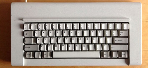
The market is growing, popularity is up, and with that comes a herculean effort to revive what could be considered the greatest keyboard of all time. This is the revival of the IBM 4704 terminal keyboard. Originally sold to banks and other institutions, this 62-key IBM Model F keyboard is rare and coveted. Obtaining one today means finding one behind a shelf in an IT closet, or bidding $500 on an eBay auction and hoping for the best.
Now, this keyboard is coming back from the dead, and unlike the IBM Model M that has been manufactured continuously for 30 years, the 62-key IBM Model F ‘Kishsaver’ keyboard is being brought back to life by building new molds, designing new circuit boards, and remanufacturing everything IBM did in the late 1970s.
Continue reading “Reviving The Best Keyboard Ever” →