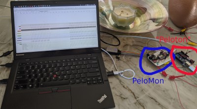
Recently [Imran Haque]’s family bought the quite popular Peloton bike. After his initial skepticism melted to a quiet enthusiasm, [Imran] felt his hacker curiosity begin to probe the head unit on the bike. Which despite being a lightly skinned android tablet, has a reputation for being rather locked down. The Peloton bike will happily collect data such as heart rate from other devices but is rather reticent to broadcast any data it generates such as cadence and power. [Imran] set out to decode and liberate the Peleton’s data by creating a device he has dubbed PeloMon. He credits the inspiration for his journey to another hacker who connected a Raspberry Pi to their bricked exercise bike.
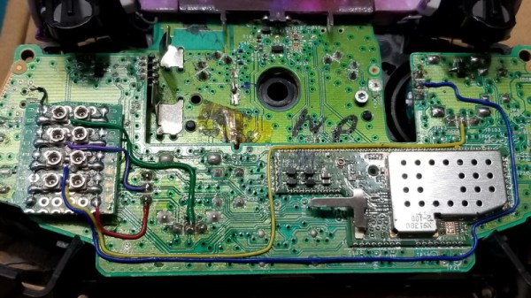
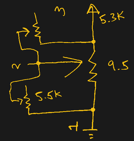
As a first step, [Imran] step began with decoding the TRRS connector that connects the bike to the head unit. With the help of a multi-meter and a logic analyzer, two 19200bps 8N1 RS-232 channels (TX and RX) were identified. Once the basic transport layer was established, he next set to work decoding the packets. By plotting the bytes in the packets and applying deductive reasoning, a rough spec was defined. The head unit requested updates every 100ms and the bike responded with cadence, power, and resistance data depending on the request type (the head unit did a round-robin through the three data types).
Once the protocol was decoded, the next step for [Imran] was to code up an emulator. It seems a strange decision to write an emulator for a device with a simple protocol, but the reasoning is quite sound. It avoids a 20-minute bike ride every time a code change needs to be tested. [Imran] wrote both an event-driven and a timing-accurate emulator. The former runs on the same board as the PeloMon and the latter runs on a separate board (an Arduino).
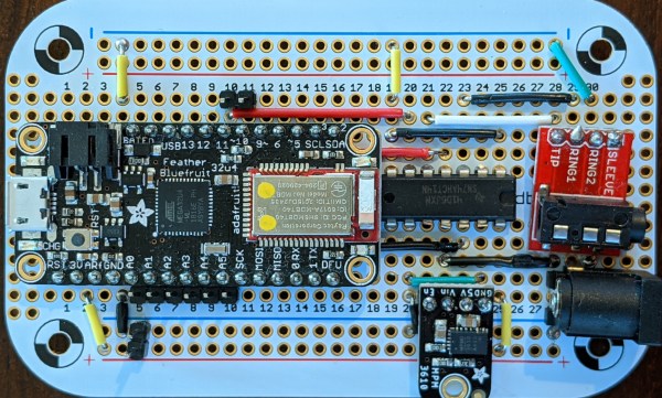
The hardware chosen for the PeloMon was an Adafruit Feather 32u4 Bluefruit LE. It was chosen for supporting Bluetooth LE as well as having onboard EEPROM. A level shifter allows the microcontroller to talk directly to the RS-323 on the bike. After a few pull requests to the Adafruit Bluetooth libraries and a fair bit of head-banging, [Imran] has code that advertises two Bluetooth services, one for speed and another for power. A Bluetooth serial console is also included for debugging without having to pull the circuit out.
The code, schematics, emulators, and research notes are all available on GitHub.