You don’t see them as often as you used to, but it used to be common to see “electronics trainers” which were usually a collection of components and simple equipment combined with a breadboard, often in a little suitcase. We think [Pro Maker_101’s] portable electronics workstation is in the same kind of spirit, and it looks pretty nice.
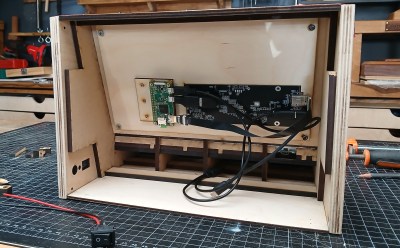
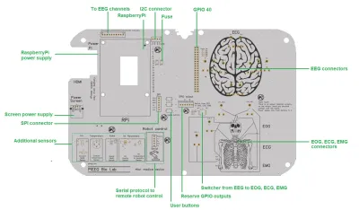
The device uses a 3D printed case and a custom PC board. There are a number of components, although no breadboard. There is a breakout board for Raspberry Pi GPIO, though. So you could use the screw terminals to connect to an external breadboard. We were thinking you could almost mount one as a sort of lid so it would open up like a book with the breadboard on one side and the electronics on the other. Maybe version two?
One thing we never saw on the old units? An HDMI flat-screen display! We doubt you’d make one exactly like this, of course, but that’s part of the charm. You can mix and match exactly what you want and make the prototyping station of your dreams. Throw in a small portable soldering iron, a handheld scopemeter, and you can hack anywhere.
We’d love to see something like this that was modular. Beats what you could build in 1974.


