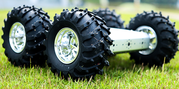
For an electronics person, building the mechanics of a robot — especially a robust robot — can be somewhat daunting. [Jithin] started with an off-the-shelf 4 wheel drive chassis to build an off-road Arduino robot he calls the Badland Brawler. The kit was a bit over $100, but as you can see in the video below, it is pretty substantial, with an enclosed frame and large mud tires.
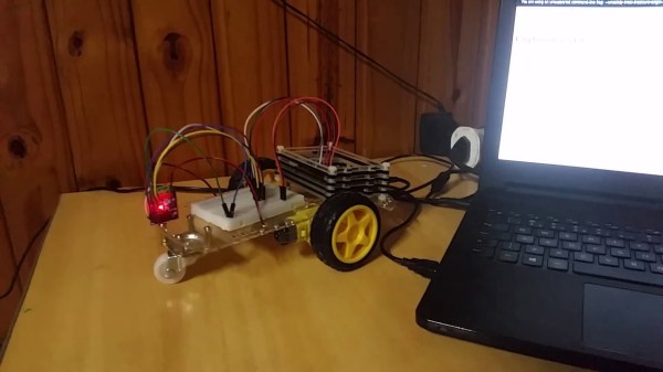
The remaining parts include an Arduino, a battery, and a motor driver IC. The Arduino is one with WiFi (an MKR 1000, in fact) and there’s a phone app for controlling the robot.
Honestly, once you have the chassis taken care of, the rest is pretty easy. Of course, the phone app is a bit more effort, but you could replace it in a number of ways. Blynk, comes to mind, for example.
The motor drivers are easy to figure out. This would be a great platform for some sensors to allow for more autonomy. We liked how the frame had mount points for a lot of different boards and sensors and could hold everything, for the most part, inside. That’s probably a good idea for a robot which will be traversing rugged terrain.
If you do decide to roll your own app with Blynk, we’ve done it with a very different kind of robot. Four-wheel drive robots don’t have to be big, as we’ve seen in the past.
Continue reading “Badland Brawler Lets Arduino Tackle Terrain”