Evolving The 3D Printed Linear Actuator

Our open source community invites anyone with an idea to build upon the works of those who came before. Many of us have encountered a need to control linear motion and adapted an inexpensive hobby servo for the task. [Michael Graham] evaluated existing designs and believed he has ideas to advance the state of the art. Our Hackaday Prize judges agreed, placing his 3D Printed Servo Linear Actuator as one of twenty winners of our Robotics Module Challenge.

[Michael]’s actuator follows in the footstep of other designs based on a rack-and-pinion gear such as this one featured on these pages, but he approached the design problem from the perspective of a mechanical engineer. The design incorporated several compliant features to be tolerant of variances between 3D printers (and slicer, and filament, etc.) Improving the odds of a successful print and therefore successful projects. Beginners learning to design for 3D printing (and even some veterans) would find his design tips document well worth the few minutes of reading time.

Another useful feature of his actuator design is the 20mm x 20mm screw mounting system. Visible on either end of the output slider, it allows mixing and matching from a set of accessories to be bolted on this actuator. He is already off and running down this path and is facing the challenge of having too many things to share while keeping them all organized and usable by everyone.

The flexible construction system allows him to realize different ideas within the modular system. He brought one item (a variant of his Mug-O-Matic) to the Hackaday + Tindie Meetup at Bay Area Maker Faire, and we’re sure there will be more. And given the thoughtful design and extensive documentation of his project, we expect to see his linear servos adopted by others and appear in other contexts as well.

This isn’t the only linear actuator we’ve come across. It isn’t even the only winning linear actuator of our Robotics Module Challenge, but the other one is focused on meeting different constraints like compactness. They are different tools for different needs – and all worthy additions to our toolbox of mechanical solutions.

Festo BionicFinWave underwater robot

[Festo]’s Underwater Robot Uses Body-Length Fins

[Festo] have come up with yet another amazing robot, a swimming one this time with an elegant propulsion mechanism. They call it the BionicFinWave. Two fins on either side almost a body-length long create a wave which pushes water backward, making the robot move forward. It’s modeled after such fish as the cuttlefish and the Nile perch.

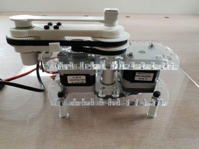
The BionicFinWave's fin mechanismWhat was their elegant solution for making the fins undulate? Nine lever arms are attached to each fin. Those lever arms are controlled by two crankshafts which extend from the front of the body to the rear, one for each side. A servo motor then turns each crankshaft. Since the crankshafts are independent, that means each fin operates independently. This allows for turning by having one fin move faster than the other. A third motor in the head flexes the body, causing the robot to swim up or down.

There’s also a pressure sensor and an ultrasonic sensor in the head for depth control and avoiding objects and walls. While these allow it to swim autonomously in its acrylic, tubular track, there is wireless communication for recording sensor data. Watch it in the video below as it effortlessly swims around its track.

[Festo] has created a lot of these marvels over the years. We’ve previously covered their bionic hopping kangaroo (we kid you not), their robot ants with circuitry printed on their exoskeleton, and perhaps the most realistic flapping robotic bird ever made.

Continue reading “[Festo]’s Underwater Robot Uses Body-Length Fins”

Wiping Robots And Floors: STM32duino Cleans Up

Ever find yourself with nineteen nameless robot vacuums lying around? No? Well, [Aaron Christophel] likes to live a different life, filled with zebra print robots (translated). After tearing a couple down, only ten vacuums remain — casualties are to be expected. Through their sacrifice, he found a STM32F101VBT6 processor acting as the brains for the survivors. Coincidentally, there’s a project called STM32duino designed to get those processors working with the Arduino IDE we either love or hate. [Aaron Christophel] quickly added a variant board through the project and buckled down.

Of course, he simply had to get BLINK up and running, using the back-light of the LCD screen on top of the robots. From there, the STM32 processors gave him a whole 80 GPIO pins to play with. With a considerable amount of tinkering, he had every sensor, motor, and light under his control. Considering how each of them came with a remote control, several infra-red sensors, and wheels, [Aaron Christophel] now has a small robotic fleet at his beck and call. His workshop must be immaculate by now. Maybe he’ll add a way for the vacuums to communicate with each other next. One robot gets the job done, but a whole team gets the job done in style, especially with a zebra print cleaner at the forefront.

If you want to see more of his work, he has quite a few videos on his website demonstrating the before and after of the project — just make sure to bring a translator. He even has a handy pinout for those looking to replicate his work. If you want to dive right in to STM32 programming, we have a nice article on how to get it up and debugged. Otherwise, enjoy [Aaron Christophel]’s demonstration of the eight infra-red range sensors and the custom firmware running them.

An Arduino Powered Tank Built To Pull Planes

Surely our readers are well aware of all the downsides of owning an airplane. Certainly the cost of fuel is a big one. Birds are a problem, probably. That bill from the traveling propeller sharpener is a killer too…right? Alright fine, we admit it, nobody here at Hackaday owns an airplane. But probably neither do most of you; so don’t look so smug, pal.

But if you did own a plane, or at least work at a small airport, you’d know that moving the things around on the ground is kind of a hassle. Smaller planes can be pulled by hand, but once they get up to a certain size you’ll want some kind of vehicle to help out. [Anthony DiPilato] wanted a way to move around a roughly 5,200 pound Cessna 310, and decided that all the commercial options were too expensive. So he built his own Arduino powered tank to muscle the airplane around the tarmac (if site is down try Google cache), and his journey from idea to finished product is absolutely fascinating to see.

So the idea here is pretty simple. A little metal cart equipped with two beefy motors, an Arduino Mega, a pair of motor controllers, and a HC-08 Bluetooth module so you can control it from your phone. How hard could it be, right? Well, it turns out combining all those raw components into a little machine that’s strong enough to tow a full-scale aircraft takes some trial and error.

It took [Anthony] five iterations before he fine tuned the design to the point it was able to successfully drag the Cessna without crippling under the pressure. The early versions featured wheels, but eventually it was decided that a tracked vehicle would be required to get enough grip on the blacktop. Luckily for us, each failed design is shown along with a brief explanation about what went wrong. Admittedly it’s unlikely any of us will be recreating this particular project, but we always love to see when somebody goes through the trouble of explaining what went wrong. When you include that kind of information, somewhere, somehow, you’re saving another maker a bit of time and aggravation.

Hackers absolutely love machines with tank treads. From massive 3D printed designs to vaguely disturbing humanoid robots, there’s perhaps no sweeter form of locomotion in the hacker arsenal.

Continue reading “An Arduino Powered Tank Built To Pull Planes”

Tables Are Turned As Robots Assemble IKEA Furniture

Hackaday pages are rife with examples of robots being built with furniture parts. In this example, the tables are turned and robots are the masters of IKEA pieces. We are not silly enough to assume that these robots unfolded the instructions, looked at one another, scratched their CPUs, and began assembling. Of course, the procedure was preordained by the programmers, but the way they mate the pegs into the ends of the cross-members is a very human thing to do. It reminds us of finding a phone charging socket in the dark. This kind of behavior is due to force feedback which tell the robots when a piece is properly seated which means that they can use vision to fit the components together without sub-millimeter precision.

All the hardware used to make the IKEA assembler is publicly available, and while it may be out of the typical hacker price range, this is a sign of the times as robots become part of the household. Currently, the household robots are washing machines, smart speakers, and 3D printers. Ten years ago those weren’t Internet connected machines so it should be no surprise if robotic arms join the club of household robots soon. Your next robotics project could be the tipping point that brings a new class of robots to the home.

Back to our usual hijinks, here is a robot arm from IKEA parts and a projector built into a similar lamp. or a 3D printer enclosed in an IKEA cabinet for a classy home robot.

Continue reading “Tables Are Turned As Robots Assemble IKEA Furniture”

FPV-Rover 2.0 Has 3D Printed Treads And Plenty Of Zip

[Markus_p] has already finished one really successful 3D printed tracked robot build. Now he’s finished a second one using standard motors and incorporating what he learned from the first. The results are pretty impressive and you can see a video demo of the beast, below.

Most of the robot is PLA, although there are some parts that use PETG and flex plastic. There is an infrared-capable camera up front and another regular camera on the rear. All the electronics are pretty much off the shelf modules like an FPV transmitter and an electronic controller for the motors. There’s a servo to tilt the camera, as you can see in the second video.

The body fits together using nuts and magnets. The robot in the video takes a good beating and doesn’t seem to fall apart so it must be sufficient. What appealed to us was the size of the thing. It looks like it would be trivially easy to mount some processing power inside or on top of the rover and it could make a great motion base for a more sophisticated robot.

We’ve seen some similar projects, of course. This tracked robot uses mind control. And OpenWheel is a great place to get treads and other locomotion designs.

Continue reading “FPV-Rover 2.0 Has 3D Printed Treads And Plenty Of Zip”

A 3D-Printed Robot Actuator

Somehow, walking robots at our level never really seem to deliver on the promise that should be delivered by all those legs. Articulation using hobby servos is simple enough to achieve, but cumbersome, slow, and not very powerful. [Paul Gould] has a plan to make a better, 3D-printed articulated robot actuator.

His solution is both novel and elegant, a fairly conventional arm geometry that has at its joints a set of brushless motors similar to but a little larger than the kind you might be more familiar with on multirotors, paired with 3D-printed cycloidal gearboxes. Magnetic encoders provide the necessary positional feedback, and the result is a unit that is both compact and powerful.

With such a range of small brushless motor controllers on the market, it’s at first sight unexpected that he’s designed his own controller board. But this gives him complete control over his software, plus the CAN bus that ties everything together. He’s given us a video which we’ve placed below the break, showing the build process, the impressive capabilities of his system, and a selection of builds including a robot dog complete with tail. This is definitely a project to watch.

Continue reading “A 3D-Printed Robot Actuator”