A current probe isn’t a very common fixture on most workbenches because they are pretty expensive. [VoltLog] looks at a fairly inexpensive current probe from Micsig. He seemed impressed with the workmanship and it looks similar to more expensive offerings. There are two models with different bandwidth numbers (800 kHz and 2 MHz). It can measure current on a 10A and 100A scale.
According to [VoltLog] comparable probes from other vendors are more expensive and have lower bandwidth. He also liked that the device powers from USB since most newer scopes will have a USB port available.
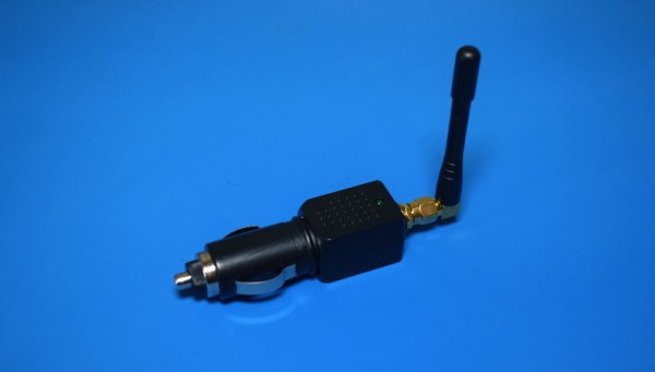
If you spend enough time trolling eBay for interesting electronic devices to take apart, you’re bound to start seeing suggestions for some questionable gadgets. Which is how I recently became aware of these tiny GPS jammers that plug directly into an automotive 12 V outlet. Shipped to your door for under $10 USD, it seemed like a perfect device to rip open in the name of science.
Now, you might be wondering what legitimate uses such a device might have. Well, as far as I’m aware, there aren’t any. The only reason you’d want to jam GPS signals in and around a vehicle is if you’re trying to get away with something you shouldn’t be doing. Maybe you’re out driving a tracked company car and want to enjoy a quick two hour nap in a parking lot, or perhaps you’re looking to disable the integrated GPS on the car you just stole long enough for you to take it to the chop shop. You know, as one does.
But we won’t dwell on the potentially nefarious reasons that this device exists. Hackers have never been too choosy about the devices they investigate and experiment with, and there’s no reason we should start now. Instead, let’s take this piece of gray-area hardware for a test drive and see what makes it tick.
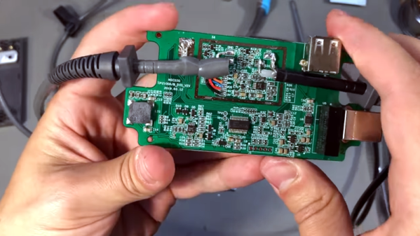
There was a time when any electronics student would have a slide rule hanging off their belt. By the 1970s, the slide rule changed over to an electronic calculator which was a pricy item. Today you can buy calculators at the dollar store. [JohnAudioTech] pulled out an old Radio Shack vacuum fluorescent display (VFD) calculator and found it didn’t work. Obviously, that means it is time to open it up.
It is fun to see one of these old devices opened up again. Consumer electronics with big through-hole ICs! Troubleshooting the device wound up being anti-climatic, as a broken wire to the battery compartment explained the whole thing.
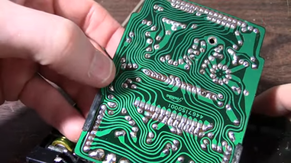
As a teardown, though, this is a fun video. Not only are all the parts through-hole, but the PCB is clearly a manual layout with serpentine traces flowing across the board like some sort of art piece. Continue reading “An Old Calculator Lives Again”→
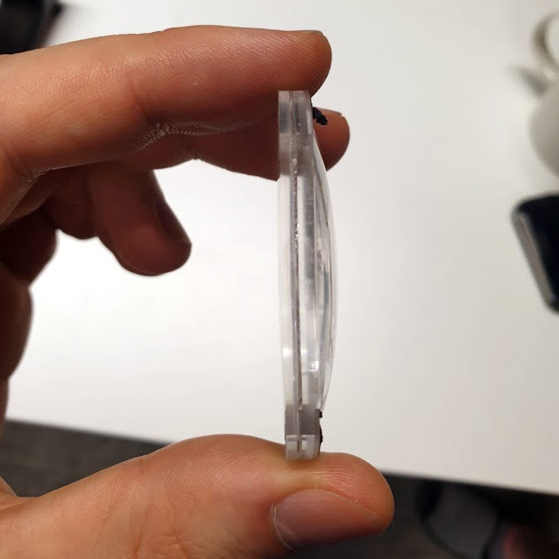
Valve’s unique multilayer lenses are far thinner than one might expect.
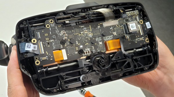
Want to see what exactly is inside the $500 (headset only price) Valve Index VR headset that was released last summer? Take a look at this teardown by [Ilja Zegars]. Not only does [Ilja] pull the device apart, but he identifies each IC and takes care to point out some of the more unique hardware aspects like the fancy diffuser on the displays, and the unique multilayered lenses (which are much thinner than one might expect.)
[Ilja] is no stranger to headset hardware design, and in addition to all the eye candy of high-res photographs, provides some insightful commentary to help make sense of them. The “tracking webs” pulled from the headset are an interesting bit, each is a long run of flexible PCB that connects four tracking sensors for each side of the head-mounted display back to the main PCB. These sensors are basically IR photodiodes, and detect the regular laser sweeps emitted by the base stations of Valve’s lighthouse tracking technology. [Ilja] also gives us a good look at the rod and spring mechanisms seen above that adjust distance between the two screens.
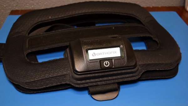
If you’ve ever had a particularly nasty fracture, your doctor may have prescribed the use of an electronic bone growth stimulator. These wearable devices produce a pulsed electromagnetic field (PEMF) around the bone, which has been shown to speed up the natural healing process in a statistically significant number of patients. That’s not to say there isn’t a debate about how effective they actually are, but studies haven’t shown any downsides to the therapy, so it’s worth trying at least.
Image from SpinalStim manual.
When you receive one of these devices, it will be programmed to only operate for a certain amount of time or number of sessions. Once you’ve “used up” the bone stimulator, it’s functionally worthless. As you might imagine, there’s no technical reason this has to be the case. The cynic would say the only reason these devices have an expiration date on them is because the manufacturer wants to keep them from hitting the second hand market, but such a debate is perhaps outside the scope of these pages.
The Orthofix SpinalStim you’re seeing here was given to me by a friend after their doctor said the therapy could be cut short. This provided a somewhat rare opportunity to observe the device before it deactivated itself, which I’d hoped would let me take a closer look at how it actually operated.
As you’ll soon see, things unfortunately didn’t work out that way. But that doesn’t mean the effort was fruitless, and there may yet be hope for hacking these devices should anyone feel like taking up the challenge.
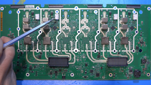
One of the best things about the Internet — especially the video part — is that you can get exposed to lots of things you might otherwise not be able to see. Take oscilloscopes, for example. If you were lucky, you might have one or two really nice instruments at work and you certainly weren’t going to be allowed to tear them open if they were working well. [The Signal Path], as a case in point, tears down a $30,000 MSO6 8 GHz oscilloscope.
Actually, the base price is not quite $30,000 but by the time you outfit one, you’ll probably break the $30K barrier. Compared to the scopes we usually get to use, these are very different. Sure, the screens are larger and denser, but looking at the circuit boards they look more like some sort of high-end computer than an oscilloscope. Of course, in a way, that’s exactly what it is.
One of the best parts about Hackaday is how much you learn from the projects that people tackle, especially when they are repairs on old gear with unknown failure modes and potentially multiple problems. By the same token, the worst part about Hackaday is seeing what other people are capable of and knowing that you’ve got a long way to go to catch up to them.
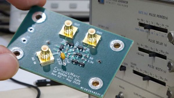
A case in point is [Curious Marc]’s recent repair of an old pulse generator. The instrument in question is an H-P 8082A, a device from a time when H-P was a place where “good engineers managed by even better engineers [wanted] to help other engineers,” as [Marc] so eloquently puts it. The instrument was capable of 250 MHz output with complete control over the amplitude, frequency, duty cycle, and rising and falling edge geometry of the pulses, in addition to being able to output double pulses. For an all-analog instrument made in 1974, it was in decent shape, and it still powered up and produced at least the square wave output. But [Marc]’s exploration revealed a few problems, which are detailed and partially addressed in the first video below.
In part two [Marc] goes after the problem behind the pulse delay function. He traced it to a bad IC, which was bad news since it was a custom H-P part using emitter-coupled logic (ECL) to achieve the needed performance that can no longer be sourced. So naturally, [Marc] decided to replace the chip with a custom circuit. The design and simulation of the circuit are detailed in part two, while the non-trivial details of designing a PCB to handle the high-speed signals take up most of part three. We found the details on getting the trace impedance just right fascinating.
In the end, [Marc]’s pulse generator was salvaged. It’ll go into service helping him probe the mysteries of vintage electronics from the Apollo era, so we’re looking forward to seeing more about this great old instrument.