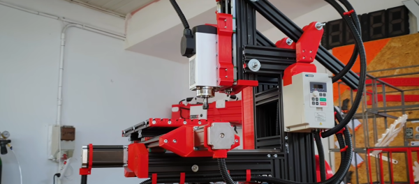
Power Supply Uses Thin Form Factor

We’ve seen lots of power supply projects that start with an ATX PC power supply. Why not? They are cheap and readily available. Generally, they perform well and have a good deal of possible output. [Maco2229’s] design, though, looks a lot different. First, it is in a handsome 3D-printed enclosure. But besides that, it uses a TFX power supply — the kind of supply made for very small PCs as you’d find in a point of sale terminal or a set-top box.

Like normal PC supplies, these are inexpensive and plentiful. Unlike a regular supply, though, they are long and skinny. A typical supply will be about 85x65x175mm, although the depth (175mm) will often be a little shorter. Compare this to a standard ATX supply at  150x86x140mm, although many are shorter in depth. Volume-wise, that’s nearly 967 cubic centimeters versus over 1,800. That allows the project to be more compact than a similar one based on ATX.

Continue reading “Power Supply Uses Thin Form Factor”

Exploring Op Amp Loading

Op amps are generally pretty easy to apply, but there are some practical nonideal behaviors you have to keep in mind. [EEforEveryone] takes a test board with some 2X amplifiers on it and — after some fiddling around with the scope probes — demonstrates the effect of capacitive loading on the output of an op amp. (Video, embedded below.)

The op amp in question is the OP07. In fact, there are two identical opamps looking at the single input. The output of one op amp feeds directly to the scope probes. The second one passes through a bipolar transistor buffer consisting of an NPN and PNP transistor. Both outputs have optional capacitors that can be jumpered in or out of the circuit.

Continue reading “Exploring Op Amp Loading”

Heads Up: Smart Glass Multimeter

Sometimes it is hard to probe a circuit and then look over at the meter. [Electronoobs] decided to fix that problem by making a Google Glass-like multimeter using an OLED screen and Bluetooth module.

The custom PCB doesn’t have many surprises. A small board has a controller, a battery charger, a display, and a Bluetooth module. One thing he did forget is a switch, though, so the board is always on unless you arrange an external switch.

Continue reading “Heads Up: Smart Glass Multimeter”

Ambitious Spot Welder Really Pushes The Amps

On the face of it, a spot welder is a simple device. If you dump enough current through two pieces of metal very quickly, they’ll heat up enough to melt and fuse together. But as with many things, the devil is in the details, and building a proper spot welder can be as much about addressing those details as seeing to the basics.

We haven’t featured anything from our friends over at [Make It Extreme], where they’re as much about building tools as they are about using them to build other things, if not more so. We expect, though, that this sturdy-looking spot welder will show up in a future video, because it really looks the business, and seems to work really well. The electronics are deceptively simple — just rewound microwave oven transformers and a simple timer switch to control the current pulse. What’s neat is that they used a pair of transformers to boost the current considerably — they reckon the current at 1,000 A, making the machine capable of welding stock up to 4 mm thick.

With the electrical end worked out, the rest of the build concentrated on the housing. A key to good-quality spot welds is solid physical pressure between the electrodes, which is provided by a leverage-compounding linkage as well as the long, solid-copper electrodes. We’ve got to say that the sweep of the locking handle looks very ergonomic, and we like the way closing down the handle activates the current pulse. Extra points for the carbon-fiber look on the finished version. The video below shows the build and a demo of what it can do.

Most of the spot welders we see are further down the food chain than this one, specialized as they are for welding battery packs and the like. We do recall one other very professional-looking spot welder, though.

Continue reading “Ambitious Spot Welder Really Pushes The Amps”

Tightly Packed Raspberry Pi Tricorder Impresses

We’ll say upfront that we don’t have nearly as much information about this 3D printed Star Trek: The Next Generation tricorder as we’d like. But from the image galleries [Himmelen] has posted we know it’s running on the Raspberry Pi Zero W, has a color LCD in addition to a monochrome OLED, and that it’s absolutely packed with gear.

So far, [Himmelen] has fit an NESDR RTL-SDR dongle, a GPS receiver, an accelerometer, and the battery charging circuitry in the top half of the case. Calling it a tight fit would be something of an understatement, especially when you take into account all the wires snaking around in there. But as mentioned in the Reddit thread about the device, a custom PCB backplane of sorts is in the works so all these modules will have something a little neater to plug into.

There are a lot of fantastic little details in this build that have us very excited to see it cross the finish line. The female USB port that’s been embedded into the top of the device is a nice touch, as it will make it easy to add storage or additional hardware in the field. We also love the keyboard, made up of 30 individual tact switches with 3D printed caps. It’s hard to imagine what actually typing on such an input device would be like, but even if each button just fired off its own program or function, we’d be happy.

Judging by the fact that the LCD shows the Pi sitting at a login prompt in all the images, we’re going to go out on a limb and assume [Himmelen] hasn’t gotten to writing much software for this little gadget yet. Once the hardware is done and it’s time to start pushing pixels though, something like Pygame could be used to make short work of a LCARS-style user interface that would fit the visual style of The Next Generation. In fact, off the top of our heads we can think of a few turn-key projects out there designed for creating Trek UIs, though the relatively limited computational power of the Pi Zero might be a problem.

We’ve seen several projects that tried to turn the iconic tricorder into a functional device. Some have focused on the arguably more recognizable Next Generation style such as this one, and others have targeted the more forgiving brick-shaped unit from Kirk and Spock’s era. The Wand Company is even working on a officially licensed tricorder that will supposedly be as close to we can get to the real thing with modern tech and a $250 USD price tag, though we’d wager COVID has slowed progress down on that one. In any event, whether you build it or buy it, the tricorder seems destined to become reality before too long.

Sanity Check Your Engines With This Dynamometer

As you get ready to pop the hood of your RC car to drop in a motor upgrade, have you ever wondered how much torque you’re getting from these small devices? Sure, we might just look up the motor specs, but why trust the manufacturer with such matters that you could otherwise measure yourself? [JohnnyQ90] did just that, putting together an at home-rig built almost from a stockpile of off-the-shelf parts.

To dig into the details, [JohnnyQ90] has built himself a Prony Brake Dynamometer. These devices are setup with the motor shaft loosely attached to a lever arm that can push down on a force-measuring device like a scale. With our lever attached, we then power up our motor. By gradually increasing the “snugness” of the motor shaft, we introduce sliding friction that “fights” the motor, and the result is that, at equilibrium, the measured torque is the maximum amount possible for the given speed. Keep turning up that friction and we can stall the motor completely, giving us a measurement of our motor’s stall torque.

Arming yourself with a build like this one can give us a way to check the manufacturer’s ratings against our own, or even get ratings for those “mystery motors” that we pulled out the dumpster. And [JohnnyQ90’s] build is a great reminder on how we can leverage a bit of physics and and a handful of home goods to get some meaningful data.

But it turns out that Prony Brake Dynamometers aren’t the only way of measuring motor torque. For a disc-brake inspired, have a look at this final project. And if you’re looking to go bigger, put two motors head-to-head to with [Jeremy Felding’s] larger scale build.


Continue reading “Sanity Check Your Engines With This Dynamometer”

High Current Measurement Probe For Oscilloscopes

A decent current measurement sensor ought to be an essential part of every hacker’s workbench. One that is capable of measuring DC, as well as low and high frequencies with reasonable accuracy. And bonus credits if it can also withstand high bus voltages – such as those found in mains utility or electric vehicle work. [Undersilicon] couldn’t find one that ticked all the boxes, so he built an ACS730 based AC/DC current probe capable of measuring up to 25 A at frequencies up to 1 MHz.

Allegro Microsystems has a wide offering of current sensor IC’s. The ACS730 features a -3 dB bandwidth of 1 MHz, and -1 dB bandwidth of 500 kHz. Since it is galvanically isolated, it can be used in AC mains applications up to 297 Vrms and for DC up to 420 V. And as he intended to use it as an oscilloscope accessory, the analog output suited the application nicely. A pair of precision op-amps provide the voltage output scaled to 100 mV/A. The board is powered off a 1000 mAh LiPo battery that can run the sensor for about 15 ~ 20 hours. The power supply section consists of a charge circuit for the LiPo, and a split rail dual output power supply converter for the op-amps.

The ACS730 has a 2.5 V output when measured current is zero, and is scaled for 40 mV/A. This gives an output voltage swing from -0.5 V for -50 A to +4.5 V for +50 A. This is where the AD823ARZ dual 16 MHz, Rail-to-Rail FET Input Amplifiers step in. One pair is used to obtain a 2.5 V reference from the 5 V supply, and also to buffer the analog output from the ACS730. The second pair subtracts the 2.5 V offset, and applies a gain of 2.5 to get the 100 mV/A output. Dual power supply for the op-amps comes from a TPS65133 Split-Rail Converter, ±5V, 250mA Dual Output Power Supply. Lastly, LiPo charging is handled by the MCP73831 Single Cell, Li-Ion/Li-Polymer Charge Management Controller.

Initial testing of direct currents has shown fairly accurate performance. But he’s observed some noise when measuring currents below 1 A which requires some debugging to figure out the source. [Undersilicon] has provided the CAD files for both the PCB and 3D printed enclosure, giving you access to everything you need to build one yourself. If you’re looking for something a bit more heavy duty, you might be interested in this +/-50 A, 1.5 MHz sensor encased in concrete.