As we’ve seen over the years, it’s possible to bootstrap your own metalworking shop using little more than a pile of scrap steel, a welder, and an angle grinder. With time and dedication, you can build increasingly complex shop tools until you’ve got yourself a nice little post-apocalyptic workshop. It’s the whole idea behind the [Workshop From Scratch] channel, and we never get bored of seeing his incredible backyard engineering.
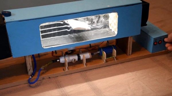
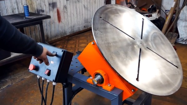
But eventually, you’ll have built all the basic stuff. What then? Well, as [Workshop From Scratch] shows in a recent video, you can start working on the luxuries. Do you need a motorized table that will let you spin the workpiece and position it an at arbitrary angle? No, probably not. But as the video after the break shows, it’s certainly a handy thing to have around the shop. We especially like how he uses it to quickly and easily produce nearly perfect circular welds.
From a technical standpoint, this is perhaps one of his more straightforward builds. But at the same time, the attention to detail that he puts into even this “simple” design is phenomenal. Nothing is wasted, and cutoff pieces from one section are often used in imaginative ways elsewhere.
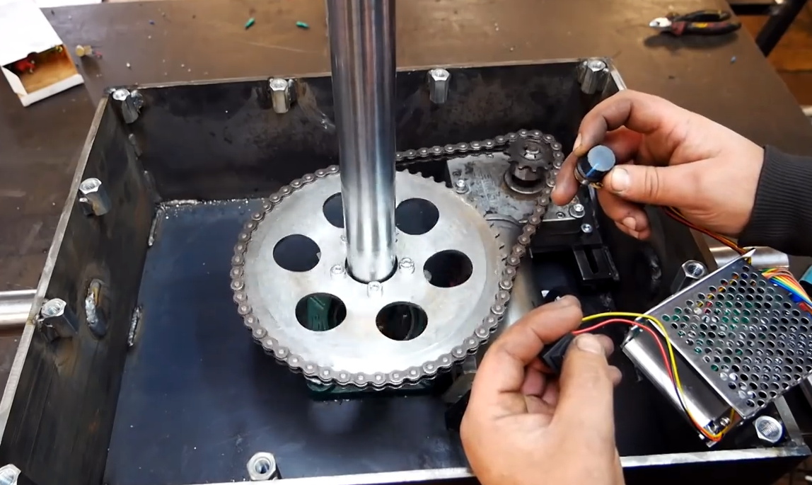
[Workshop From Scratch] is truly a master of working with what you have, and this project is a perfect example. We especially like the tilt mechanism, which uses a massive leadscrew spun by a wiper motor salvaged from an Audi A8 B4. It looks like a fair amount of new hardware went into the control electronics, but even still, we have no doubt that the cost of this build is well below the purchase price of a commercial alternative.
Much like his hydraulic lifting table or motorized plasma cutter, not everyone is going to need something this elaborate in their home shop. But his magnetic vise and mobile drill press cart are far more approachable for the home gamer. Of course even if you don’t follow along and build your own versions of his tools, it’s always worth tuning in just to see him work.
Continue reading “A Motorized Rotary Shop Table From Scratch”