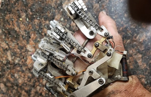
A DIY Electronics Lab You Can Show Off With Pride

It’s hardly a secret that getting into a serious electronics habit can be detrimental to your bank account. A professional grade lab is simply unobtainable for many a tinkerer, and even mid-range hardware can set you back considerably. Which is why many folks just starting out will attempt to salvage or build as much of their equipment as possible. It might not always be pretty, but it’ll get the job done.

But this project by [Chrismettal] could end up completely reinventing the home electronic workspace. Using 3D printed frames, low-cost components, and a sprinkling of custom PCBs, this modular electronics workbench has all the bells and whistles an aspiring hardware hacker could need. As an added bonus, it looks like something that came off the International Space Station.

Inside the resistor substitution module.

This is one of those projects that simply can’t be done justice in a few paragraphs. If you’ve ever wanted to put together a dedicated electronics workbench but were put off by the cost of individual components, read though the fantastic documentation [Chrismettal] has prepared for the EleLab_v2. Is it all top-of-the-line hardware? No, of course not. But it’s more than suitable for the kind of work people in this community usually find themselves involved in on a weekend.

So what’s included? Naturally [Chrismettal] has created a power supply module, in both variable and fixed flavors. But there’s also a module for a resistor substitution, a component tester, and even a digital storage oscilloscope. You can mix and match the modules suit your needs, and if you want to create entirely new ones, the FreeCAD sources are available to get you started.

We’ve seen low-cost power supply modules before, and naturally we’re no strangers to cheap DSO kits. But this project wraps those devices and gadgets up into a form factor that anyone would be happy to have on their bench. We’re exceptionally interested in seeing new modules developed for the EleLab_v2, and doubt this is the last time you’ll see this impressive project grace these pages.

[Thanks to BrunoC for the tip.]

Ironclad Tips For Copper-Clad Prototyping

The idea of trying to prototype with SMD parts on the fly sounds like insanity, right? But then we watched [Leo Fernekes] walk calmly and carefully through his process (video, embedded below). Suddenly, SMD prototyping jumped onto our list of things to try soon.

[Leo] speaks from a lot of experience and tight client timelines, so this video is a fourteen-minute masterclass in using copper-clad board as a Manhattan-style scratch pad. He starts by making a renewable tool for scraping away copper by grinding down and shaping an old X-Acto blade into a kind of sharpened Swiss Army knife bottle opener shape. That alone is mind-blowing, but [Leo] keeps on going.

In these prototypes, he uses the through-hole version of whatever microcontroller is in the design. For everything else, he uses the exact SMT part that will end up on the PCB that someone else is busy designing in the meantime.

After laying the board out on paper, [Leo] carves out the islands of conductivity, beep-checks them for shorts, shines the whole thing with steel wool, and goes to town.

The tips and tricks keep coming as he makes jumps and joins ground planes with bare copper wire insulated with heat-proof Teflon tubing, and lays out the benefits of building up a stash of connectors and shelling out the money for a good crimp tool.

And why do you need a good crimp tool? Because when they’re done properly, crimped connections are stronger and more reliable than solder. There’s a lot more to them than you might think.

Continue reading “Ironclad Tips For Copper-Clad Prototyping”

Finding RF Cable Impedance

At DC and low frequency, we can pretend wires are perfect conductors. At radio frequencies, though, there are many effects that you need to take into account for wires and cables. One of these is characteristic impedance. If you have a marked cable, you can look it up on the Internet, of course. But what if you don’t know what kind of wire it is? With help from [The Offset Volt], you can measure it as he shows in the video below.

This is one of those things that used to take exotic test equipment like an LCR bridge, but these days meters that measure inductance and capacitance are commonplace. The trick is simple: measure the capacitance and then short one end of the cable and measure the inductance.

Continue reading “Finding RF Cable Impedance”

Resistors Sorter Measures Values

We’ve all been there. A big bag of resistors all mixed up. Maybe you bought them cheap. Maybe your neatly organized drawers spilled. Of course, you can excruciatingly read the color codes one by one. Or use a meter. But either way, it is a tedious job. [Ishann’s] solution was to build an automatic sorter that directly measures the value using a voltage divider, rather than rely on machine vision as is often the case in these projects. That means it could be modified to do matching for precise circuits (e.g., sort out resistors all marked 1K that are more than a half-percent away from one nominal value).

There is a funnel that admits one resistor at a time into a test area where it is measured. A plate at the bottom rotates depending on the measured value. In the current implementation, the resistor either falls to the left or the right. It wouldn’t be hard to make a rotating tray with compartments for different values of resistance. It looks like you have to feed the machine one resistor at a time, and automating that sounds like a trick considering how jumbled loose axial components can be. Still, its a fun project that you probably have all the parts to make.

An Arduino powers the thing. An LCD screen and display control the action. If you want some practice handling material robotically, this is a great use of servos and gravity and it does serve a practical purpose.

We have seen many variations on this, including ones that read the color code. If you ever wanted to know where the color code for resistors came from, we took a trip to the past to find out earlier this year.

Continue reading “Resistors Sorter Measures Values”

Old School Rotary Tools That Weren’t Made By Dremel

Albert Dremel developed the now famous rotary tool and started the company in 1932 to make blade sharpeners. It would be 1935 before the company produced the Moto-Tool which is mostly recognizable as an ancestor of the modern Dremel.

Dremel achieved such dominance that today the name is synonymous with rotary tools in the same way Xerox means photocopy and Crock-Pot is any slow cooker. Sure, there are knock offs you can get from the usual cheap tool outlets, but generally, people reach for a Dremel even when it isn’t really one. Today that tool might really be a Black and Decker or a Dewalt or even a cheap brand like Wen or Chicago Electric. But in the first half of the 20th century, you might have reached for a Handee.

A Whole Shop Full of Tools

The Handee was a product of the Chicago Wheel and Manufacturing Company who, in 1937, billed it as “a whole shop full of tools in one,” as you can see in this ad. While $10.75 might sound like a price for a Harbor Freight cheapie tool, adjusted for inflation that’s around $200 in 2020 money. At least for that price you got three free accessories out of the over 200 available.

I didn’t remember the Handee and I wanted to see if I could figure out what happened to it and the company who made it. After all, with the Internet at your disposal, how hard could it be? Turns out, I did learn a lot, but in the end, tracing down a company like this from the old days isn’t always as easy as you might think.

Continue reading “Old School Rotary Tools That Weren’t Made By Dremel”

Blinkenlights For Your Parallel Port

Most modern equipment is connected over USB, and generally speaking we’re all the better for it. But that’s not to say there aren’t some advantages to using serial and parallel ports. For example, the slower and less complex protocols can be a bit easier to debug when devices aren’t communicating, which [Jeremy Cook] demonstrates in his latest project.

Looking to troubleshoot some communications problems he was having between his computer and CNC router, [Jeremy] came up with a handy little gadget that will allow him to visualize data passing through each pin of the parallel port in real-time. Even from across the room he can tell at a glance if communication is active, and with a keen eye, determine if he’s getting bi-directional traffic or not.

From a technical standpoint, this is a pretty simple project. The custom PCB is essentially just a pass-through, with an array of 3 mm LEDs and matching 10K resistors hanging off the data lines. But [Jeremy] found it to be an excellent excuse to brush up his KiCad skills. As he explains in the video after the break, this project certainly won’t impress the folks that do PCB design on a daily basis; but if you’re still learning the ropes, these are precisely the kind of projects you should be looking for.

Before any of you say it in the comments, we already know devices like this are available commercially for a few bucks. But that’s hardly the point. Things would be awfully slow around these parts if we disregarded any project that had a commercial alternative.

Continue reading “Blinkenlights For Your Parallel Port”

Open Source Pick And Place Has A $450 BOM Cost

Give your grizzled and cramped hands a break from stuffing boards with surface mount components. This is the job of pick and place machine, and over the years these tools of the trade for Printed Circuit Board Assembly (PCBA) have gotten closer to reality for the home shop; with some models diving below the $10,000 mark. But if you’re not doing it professionally, those are still unobtanium.

The cost of this one, on the other hand, could be explained away as a project in itself. You’re not buying a $450 shop tool, you’re purchasing materials to chase the fever dream of building an open source pick and place machine. There are two major parts here, an X/Y/Z machine tool that can also rotate the vacuum-based parts picker, and the feeders that reel out components to be placed. All of this is working, but there’s still a long road to travel before it becomes a set and forget machine.

The rubber hits the road in two ways with pick and place machines: the feeders, and the optical placement. The feeders are where [Stephen Hawes] has done a ton of work, all shown in his video series that began back in January. The stackup of PCBs and 3D-prints hangs on the front rail of the gantry assembly, is adjustable for tape widths, and uses an interesting PCB encoder wheel and worm-gear for fine-tuning the feed. [Stephen’s] main controller board, a RAMPS shield for and Arduino Mega that runs a customized version of Marlin, can work with up to 32 of these feeders.

So far it doesn’t look like he’s tackled a vision system, although the Bill of Materials does include  “Downwards Camera”, confirming this is a planned feature. Vision is crucial in commercial offerings, with at least one downward camera for precise board positioning, and often an up-facing camera as well to ensure component position and orientation (if not multiple cameras for each purpose). Without these, the machine would be dead reckoning and that can lead to drift over the size of the board and the duration of the placement run as well as axial misalignment. Adding vision shouldn’t be a ground-up effort though, as [Stephen] chose to use OpenPnP to drive the machine and that project already has vision support. This will be much simpler to add when compared to the complexity of the feeders.

[Stephen] admits that much work still needs to be done and he would love to have help dialing in the performance of the feeder design, and fleshing out features on the road to perfection. Although we suspect that as in the early days of bootstrapping 3D printers, a project like this can never be truly finished. At least it’ll make his next run of LED glowties a lot easier to fabricate.

Continue reading “Open Source Pick And Place Has A $450 BOM Cost”