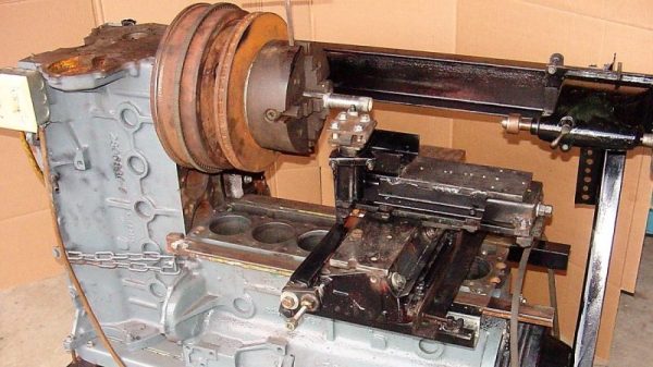
Antique Lighthouse Lens Via CNC

Before the invention of the high-powered LED, and even really before the widespread adoption of electric lights in general, lighthouses still had the obligation of warning ships of dangers while guiding them into various safe harbors. They did this with gas lights and impressive glass lenses known as Fresnel lenses which helped point all available light in the correct direction while reducing weight and material that would otherwise be used in a conventional lens.

Now, a company in Florida is using acrylic in reproductions of antique Fresnel lenses. At first glance, it seems like acrylic might not be the best substitute for glass, but the company is able to achieve extreme precision using a CNC machine and then polishing and baking the acrylic which makes it transparent and excellent for use in lighthouse lenses like this. The reproduction lenses are built out of brass, and the lens elements are glued in place with a special adhesive. It’s a convincing replication worthy of use in any lighthouse.

Be sure to check out the video below to see how these lenses are built, and although we’re not entirely sure what exactly is being sprayed on the lenses when they are being polished, perhaps someone in the comments section can illuminate that for us. Of course, there are other uses for Fresnel lenses than in lighthouses, and we’ve seen some great examples of them put to use for many different applications.

Continue reading “Antique Lighthouse Lens Via CNC”

Soundproofing A CNC Mill Conversion

The Proxxon MF70 is a nice desktop sized milling machine with a lot of useful add-on accessories available for it, making it very desirable for a hacker to have one in his or her home workshop. But its 20000 rpm spindle can cause quite the racket and invite red-faced neighbors. Also, how do you use a milling machine in your home-workshop without covering the whole area in metal chips and sawdust? To solve these issues, [Tim Lebacq] is working on Soundproofing his CNC mill conversion.

To meet his soundproof goal, he obviously had to first convert the manual MF70 to a CNC version. This is fairly straightforward and has been done on this, and similar machines, in many different ways over the years. [Tim] stuck with using the tried-and-tested controller solution consisting of a Raspberry Pi, an Arduino Uno and a grbl shield sandwich, with stepper motor drivers for the three NEMA17 motors. The electronics are housed inside the reclaimed metal box of an old power supply. Since the Proxxon MF70 is already designed to accept a CNC conversion package, mounting the motors and limit switches is pretty straightforward making it easy for [Tim] to make the upgrade.

Soundproofing the box is where he faced unknown territory. The box itself is made from wooden frames lined with particle board. A pair of drawer slides with bolt-action locks is used for the front door which opens vertically up. He’s also thrown in some RGB strips controlled via the Raspberry-Pi for ambient lighting and status indications. But making it soundproof had him experimenting with various materials and techniques. Eventually, he settled on a lining of foam sheets topped up with a layer of — “bubble wrap” ! It seems the uneven surface of the bubble wrap is quite effective in reducing sound – at least to his ears. Time, and neighbours, will tell.

Maybe high density “acoustic foam” sheets would be more effective (the ones similar to “egg crate” style foam sheets, only more dense)? Cleaning the inside of the box could be a big challenge when using such acoustic foam, though. What would be your choice of material for building such a sound proof box? Let us know in the comments below. Going back many years, we’ve posted about this “Portable CNC Mill” and a “Mill to CNC Conversion” for the Proxxon MF70. Seems like a popular machine among hackers.

GPS synchronized Nixie tube clock from kit

3D Printed Tool Tips To Straighten DIP Chips And Unstraighten Resistors

Watching someone assemble a kit is a great way to see some tools you may have not encountered before and maybe learn some new tricks. During [Marco Reps’] recent build of a GPS synchronized Nixie clock kit we spied a couple of handy tools that you can 3D print for your own bench.

Fresh from the factory Dual Inline Package (DIP) chips come with their legs splayed every so slightly apart — enough to not fit into the carefully designed footprints on a circuit board. You may be used to imprecisely bending them by hand on the surface of the bench. [Marco] is more refined and shows off a neat little spring loaded tool that just takes a couple of squeezes to neatly bend both sides of the DIP, leaving every leg the perfect angle. Shown here is a 3D printed version called the IC Pin Straightener that you can throw together with springs and common fasteners.

Another tool which caught our eye is the one he uses for bending the metal film resistor leads: the “Biegelehre” or lead bending tool. You can see that [Marco’s] tool has an angled trench to account for different resistor body widths, with stepped edges for standard PCB footprint spacing. We bet you frequently use the same resistor bodies so 3D printing is made easier by using a single tool for each width. If you really must copy what [Marco] is using, we did find this other model that more closely resembles his.

As for new tricks, there are a lot of small details worth appreciating in the kit assembly. [Marco] cleans up the boards using snips to cut away the support material and runs them over sandpaper on a flat surface. Not all Nixie tubes are perfectly uniform so there’s some manual adjustment there. And in general his soldering practices are among the best we’ve seen. As usual, there’s plenty of [Marco’s] unique brand of humor to enjoy along the way.

We have a warm spot in our heart for simple tools you can whip up on the ‘ole 3D printer. Check out the PCB vise, a set of ball and socket helping hands, and a collection of toolbag essentials.

Continue reading “3D Printed Tool Tips To Straighten DIP Chips And Unstraighten Resistors”

Diagram generated by QElectroTech

QElectroTech: An Open Source Wiring Diagram Tool

There’s a few open source options out there for creating electrical schematics. KiCad and Fritzing are two that will take you from schematic capture to PCB layout. However, there’s been limited options for creating wiring diagrams. Often these are created in Microsoft’s Visio, which is neither open source nor well suited for the task.

QElectroTech is an open source tool for drawing these types of diagrams. It consists of two tools: an element editor for creating schematic symbols and a diagram editor for creating your drawings. Libraries of common symbols are also included, along with the IEC 60617 standardized symbols.

Being a schematic editor, QElectroTech does a good job of drawing clean connections between components. Connections are automatically routed at 90 degree angles and are easy to drag around. Systems made up of more than just electrical connections are also a good fit for the software. Here you can see piping and manual valves as well as electronic sensors and actuators all in the same diagram.

Next time you need to document the wiring of something, QElectroTech is a good option to try. It’s been around since 2008 it is under active development, and there are Windows, OSX and Linux version (including a PPA for nightly builds) available.

Putting The Mooshimeter To Sleep With A Bit Of Mercury

If you haven’t heard of it, the Mooshimeter is a two channel multimeter that uses your smartphone as a display over Bluetooth 4.0. The ability to simultaneously monitor voltage and current is rather unique, and the fact that you aren’t physically tethered to the thing makes it ideal for use in hard to reach or even dangerous locations. The promotional material for the Mooshimeter shows users doing things like leaving the device inside the engine compartment of a car while they drive around and take readings about the vehicle’s electrical system.

Note the vertical orientation

All that sounds well and good, but at the end of the day, the Mooshimeter is probably not going to be your primary multimeter. It’s going to stay on a shelf until a task befitting its unique abilities comes along. Unfortunately, as [nop head] found, that can be a problem. Like many modern devices, the Mooshimeter doesn’t actually turn off. It just sits there draining its battery until you’re ready to use it. Which of course means that when you’re finally ready to pull the thing out and put it to use, you get a low battery warning and need to put new AAs in it. First World problems.

The fix for this thoroughly modern problem is delightfully old school: a mercury tilt switch.

Using a small spacer made of Kapton tape, [nop head] was able to isolate the battery contacts from the PCB itself. He then soldered the mercury switch in place between them, making sure to position the bulb vertically. When the Mooshimeter is right side up, the mercury flows down and bridges the contacts; but when the device is inverted the contact is broken and the batteries stop draining. He still has to remember to put the Mooshimeter face down when he’s done with it, but it’s better than dealing with constant dead batteries.

There was a lot of initial interest in the Mooshimeter when it was announced in 2014, but we’ve seen precious little of it since. It certainly seems neat, but perhaps it’s a bit too niche for its own good? If Mooshimeter fulfills a critical role in your tool set, let us know in the comments below.

Printed It: Toolbag Essentials

While complex devices assembled from 3D printed components are certainly impressive, it’s the simple prints that have always held the most appeal to me personally. Being able to pick an object up off the bed of your printer and immediately put it to use with little to no additional work is about as close as we can get to Star Trek style replicators. It’s a great demonstration to show off the utility of your 3D printer, but more importantly, having immediate access to some of these tools and gadgets might get you out of a jam one day.

With that in mind, I thought we’d do things a little differently for this installment of Printed It. Rather than focusing on a single 3D model, we’ll be taking a look at a handful of prints which you can put to practical work immediately. I started by selecting models based on the idea that they should be useful to the average electronic hobbyist in some way or another, and relatively quick to print. Each one was then printed and evaluated to determine its real-world utility. Not all made the grade.

Each model presented here is well designed, easy to print, and most critically, legitimately useful. I can confidently say that each one has entered into my standard “bag of tricks” in some capacity, and I’m willing to bet a few will find their way into yours as well.

Continue reading “Printed It: Toolbag Essentials”

Ham Reviews MiniVNA

[KB9RLW] wanted to build a vector network analyzer (VNA), but then realized he could buy a ready-made one without nearly the cost it would have been only a few years ago. The network in this case, by the way, is an electrical network, not a computer network. You can use a VNA to characterize components, circuits, antennas, and even feed lines at different frequencies. The miniVNA Pro is economical and can exercise circuits from 1 MHz to 3 GHz. You can see the review in the video below.

There are a few ways to actually create a VNA, but in concept, it is a sweep generator, a detector, and a means to plot the response at each frequency in the sweep. So you’d expect, for example, a resonant frequency to show a peak at resonance and a band reject filter to show a low point.

One of the things interesting about the device is that it uses Java software. That means it doesn’t care much what platform you want to use. The software can show two different plots at once, so [Kevin] hooks it to his 20 meter antenna and shows how it can plot the SWR and impedance around the frequency of interest.

The instrument can be USB powered with the same cable you use to connect the PC. However, it also has an internal rechargeable battery. That battery charges on USB and can operate the device with Bluetooth. We can imagine that being handy when you want to climb up a tower and connect it directly to an antenna as long as you stay in Bluetooth range of the PC. There’s also a phone app, so you can go that route, if you prefer and [Kevin] shows the device working with Android. Of course, you could probably rig a Raspberry Pi on your belt and then use WiFi to let someone on the ground remote desktop in to run measurements. A lot of possibilities.

If you want to roll your own, that’s possible, of course. If you want to get by a bit cheaper, there are less expensive options.

Continue reading “Ham Reviews MiniVNA”