We know, you’ve already got a USB to serial adapter. Probably several of them, in fact. But that doesn’t mean you couldn’t use one more — especially when it’s as as cleverly designed as this one from [Anders Nielsen].
The first thing you notice about this adapter, and the big departure from the ones that are likely littering your parts bin, is that it terminates in a full-size male DSUB9 connector. With the ability to be directly plugged into a RS-232 port, this adapter will certainly catch the eye of retrocomputer enthusiasts. With a clever arrangement of jumpers, you can even reconfigure the RX and TX lines to be straight-through or cross over as needed.
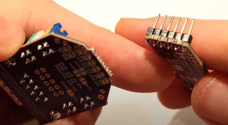 But if you’re working with something that doesn’t have a literal serial port, no worries. All of the lines coming from the CH340G chip are broken out to a header so you can connect it up to whatever device you’re working with via jumpers.
In fact, if you’re really sure you’ll never need that RS232 feature, the PCB is even designed in such a way that you can simply snap it off. Admittedly it might seem a little odd to get a device like this if you didn’t want that capability. But once broken off, it’s not like the components go to waste. [Anders] has designed the board in such a way that if you flip it over and install a right-angle header, you can use the RS232 segment on a breadboard.
But the list of features doesn’t stop there. There’s also a 3.3 V regulator on board that you can use to power external circuits, as well as breakouts for the data lines in the USB-C connector. In keeping with the theme of the device, that part of the PCB can also be snapped off if you want to use it elsewhere.
Most folks probably’ won’t need all the capabilities offered by this particular serial adapter, and that’s fine. We’re still happy that it’s out in the wild and available for the community to use and adapt as an open source project.
Continue reading “Break Me Off A Piece Of That Open Source Serial Adapter”