Interested in experimenting with your own multi-color filament? [Turbo_SunShine] says to just print your own, and experiment away! Now, if you’re thinking that 3D printing some filament sounds inefficient at best (and a gimmick at worst) you’re not alone. But there’s at least one use case that it makes sense for, and maybe others as well.
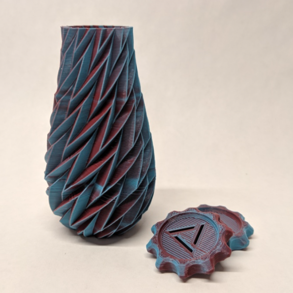
There is such a thing as bi-color filament (like MatterHackers Quantum PLA) which can be thought of as filament that is split down the center into two different colors. Printing with such filament can result in some trippy visuals, like objects whose color depends in part on the angle from which they are viewed. Of course, for best results it makes sense to purchase a factory-made spool, but for light experimenting, it’s entirely possible to 3D print your own bi-color filament. Back when [Turbo_SunShine] first shared his results, this kind of stuff wasn’t available off the shelf like it is today, but the technique can still make sense in cases where buying a whole spool isn’t called for.
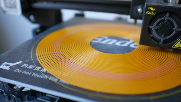
Here is how it works: the 3D model for filament is a spiral that is the right diameter for filament, printed as a solid object. The cross-section of this printed “filament” is a hexagon rather than a circle, which helps get consistent results. To make bi-color filament, one simply prints the first half of the object in one color, then performs a color change, and finishes the print with a second color. End result? A short coil of printed “filament”, in two colors, that is similar enough to the normal thing to be fed right back into the printer that created it. This gallery of photos from [_Icarus] showcases the kind of results that are possible.
What do you think? Is 3D printing filament mainly an exercise in inefficiency, or is it a clever leveraging of a printer’s capabilities? You be the judge, but it’s pretty clear that some interesting results can be had from the process. Take a few minutes to check out the video (embedded below) for some additional background.