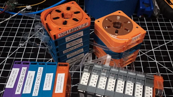
[Kadah]’s solution for storing short tapes of SMT parts is as attractive as it is clever. The small 3D-printed “tape reels” can double as dispensers, and stack nicely onto each other thanks to the sockets for magnets. The units come in a few different sizes, but are designed to stack in a consistent way.
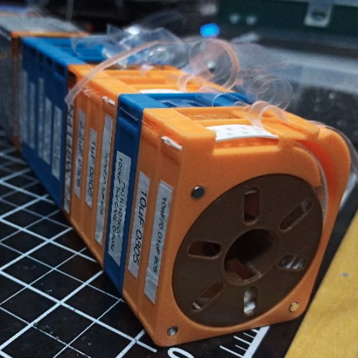 We love the little touches such as recessed areas for labels, and the fact that the parts can print without supports (there are a couple of unsupported bridges, but they should work out fine.) Also, the outer dimensions of the units are not an accident. They have been specifically chosen to nestle snugly into the kind of part drawers that are a nearly ubiquitous feature of every hardware hacker’s work bench.
STLs are provided for handy download but [Kadah] also provides the original Fusion 360 design file, with all sizes defined as easily-customized parameters. In addition, [Kadah] thoughtfully provided each model in STEP format as well, making it easy to import and modify in almost any 3D CAD program.
Providing 3D models in STEP format alongside STLs is nice to see, because it gives more options to people if things need some tweaking, because editing the STL file can be done if needed, but isn’t optimal. Thankfully the ability to export STEP files is still open to hobbyists using Fusion 360, since Autodesk decided to leave that feature available to personal use licenses.